


3-25
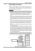
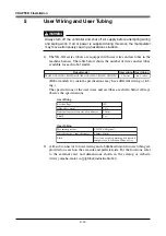
CHAPTER 3 Installation
6-4
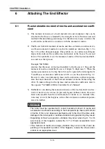
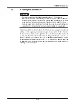
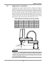
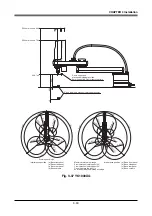
Attaching the end effector
WARNING
• Before attaching the end effector, be sure to turn off the controller.
• When the end effector is attached by slot clamping, always observe the con-
ditions listed in Table 3-2. If these are ignored, the end effector may come
loose and fly off during robot operation, resulting in an accident or injury.
• In cases where other attachment methods are used, be sure that the end
effector will not come off when the loads listed in Table 3-1 are applied.
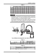
The user's end effector that attaches to the robot must have adequate strength and
rigidity, as well as gripping force to prevent positioning errors. Table 3-1 shows
the maximum load that can be applied to the end effector attachment of each
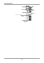
robot model. Recommended methods for attaching end effectors are shown in
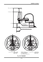
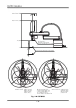
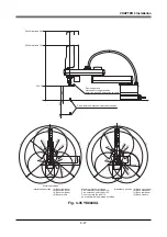
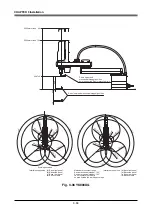
Table 3-2 and Fig. 3-27. Refer to Fig. 3-25 for details on the end effector attach-
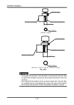
ment of each robot model. Refer to Fig. 3-3 for the depth of tapped hole and
recommended type of tap bolt. When checking end effector operation, refer to "6
Trial Operation" in Chapter 1.
Summary of Contents for YK-X Series
Page 1: ...User s Manual ENGLISH E YAMAHA SCARA ROBOT E35 Ver 1 08 YK XG YK X series ...
Page 2: ......
Page 6: ...MEMO ...
Page 10: ...MEMO ...
Page 12: ...MEMO ...
Page 30: ...MEMO ...
Page 36: ...MEMO ...
Page 46: ...3 10 CHAPTER 3 Installation Ground symbol M4 Ground terminal Fig 3 6 Ground terminal ...
Page 78: ...3 42 MEMO ...
Page 80: ...MEMO ...
Page 101: ...4 21 CHAPTER 4 Adjustment Cover Elongated hole Y axis origin sensor stay Bolt Fig 4 8 a ...
Page 102: ...4 22 CHAPTER 4 Adjustment Dog Hex nut Fig 4 8 b Bolt Y axis arm X axis arm Fig 4 8 c ...
Page 119: ...4 39 CHAPTER 4 Adjustment R End effector End effector Z Y X Fig 4 18 ...
Page 120: ...4 40 MEMO ...
Page 122: ...MEMO ...
Page 138: ...5 16 CHAPTER 5 Periodic Inspection M6 16 M5 16 X axis motor Base Fig 5 3 ...
Page 146: ...5 24 CHAPTER 5 Periodic Inspection M3 16 M4 18 X axis arm Fig 5 10 ...
Page 155: ...5 33 CHAPTER 5 Periodic Inspection O ring r M5 14 M6 16 R axis motor Fig 5 17 ...
Page 156: ...5 34 CHAPTER 5 Periodic Inspection M3 14 M3 16 O ring w Fig 5 18 ...
Page 161: ...CHAPTER 6 Increasing the robot operating speed 1 Increasing the robot operating speed 6 1 ...
Page 162: ...MEMO ...
Page 168: ...6 6 MEMO ...
Page 170: ...MEMO ...
Page 177: ...MEMO ...


