


3-31
CHAPTER 3 Installation
7-1
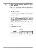
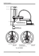
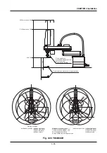
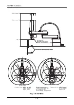
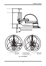
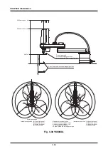
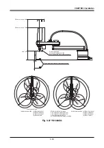
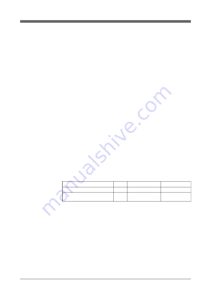
YK500XG, YK600XG, YK600XGH, YK700XG, YK800XG,
YK900XG, YK1000XG
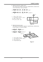
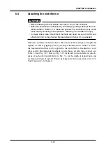
To change the X-axis mechanical stopper positions, for example, from the maxi-
mum movement range (132
°
) to 87
°
, use the following procedure.
1) Prepare a hex wrench set.
2) Turn off the robot controller.
3) Place a sign indicating the robot is being adjusted, to keep others from touch-
ing the controller switch.
4) Enter the safeguard enclosure.
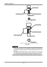
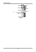
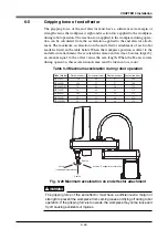
5) Remove the screw plug, X-axis mechanical stopper bolt and washer as shown
in Fig. 3-30. Then reinstall the mechanical stopper bolt and washer at the
position that determines the desired movement range by tightening the bolt
to the torque specified in Table 3-5.
Reinstall the screw plug you removed, into the position where the X-axis
stopper bolt was installed.
6) Check that the movement range is limited by the mechanical stoppers as
desired.
7) Go outside the safeguard enclosure.
8) Check that no one is inside the safeguard enclosure when turning on the
controller.
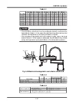
Table 3-5
Bolt size Tightening torque (kgfcm) Tightening torque (Nm)
M8
380
37.2
M10
459
45.0
Robot Model
YK500XG,YK600XG
YK600XGH, YK700XG, YK800XG,
YK900XG, YK1000XG
Use only YAMAHA genuine bolts or JIS B 1176 hex socket head bolts
(strength class: JIS B 1051 12.9).
Summary of Contents for YK-X Series
Page 1: ...User s Manual ENGLISH E YAMAHA SCARA ROBOT E35 Ver 1 08 YK XG YK X series ...
Page 2: ......
Page 6: ...MEMO ...
Page 10: ...MEMO ...
Page 12: ...MEMO ...
Page 30: ...MEMO ...
Page 36: ...MEMO ...
Page 46: ...3 10 CHAPTER 3 Installation Ground symbol M4 Ground terminal Fig 3 6 Ground terminal ...
Page 78: ...3 42 MEMO ...
Page 80: ...MEMO ...
Page 101: ...4 21 CHAPTER 4 Adjustment Cover Elongated hole Y axis origin sensor stay Bolt Fig 4 8 a ...
Page 102: ...4 22 CHAPTER 4 Adjustment Dog Hex nut Fig 4 8 b Bolt Y axis arm X axis arm Fig 4 8 c ...
Page 119: ...4 39 CHAPTER 4 Adjustment R End effector End effector Z Y X Fig 4 18 ...
Page 120: ...4 40 MEMO ...
Page 122: ...MEMO ...
Page 138: ...5 16 CHAPTER 5 Periodic Inspection M6 16 M5 16 X axis motor Base Fig 5 3 ...
Page 146: ...5 24 CHAPTER 5 Periodic Inspection M3 16 M4 18 X axis arm Fig 5 10 ...
Page 155: ...5 33 CHAPTER 5 Periodic Inspection O ring r M5 14 M6 16 R axis motor Fig 5 17 ...
Page 156: ...5 34 CHAPTER 5 Periodic Inspection M3 14 M3 16 O ring w Fig 5 18 ...
Page 161: ...CHAPTER 6 Increasing the robot operating speed 1 Increasing the robot operating speed 6 1 ...
Page 162: ...MEMO ...
Page 168: ...6 6 MEMO ...
Page 170: ...MEMO ...
Page 177: ...MEMO ...


