


4-5
CHAPTER 4 Adjustment
3-3
Absolute reset procedures
3-3-1
Sensor method (X-axis, Y-axis, and R-axis)
WARNING
Serious injury might occur from physical contact with the robot during opera-
tion. Never enter within the robot movement range during absolute reset.
The operation procedure using the MPB is described next. (Press the ESC key on
the MPB if you want to return to the preceding step.) See the "YAMAHA Robot
Controller User's Manual" for information on operating the robot controller.
1) Check that no one is inside the safeguard enclosure and then turn on the
controller.
2) Place a sign indicating the robot is being adjusted, to keep others from touch-
ing the controller switch or operation panel.
3) Set the controller to MANUAL mode, if not in MANUAL mode.
4) Press the F13 (LOWER+F3) key to select "RST. ABS".
5) Select the axis for absolute reset. (X-axis: M1, Y-axis: M2, R-axis: M4)
To perform absolute reset on all axes, select "ALL" with the F11 (LOWER+F1)
key.
!
CAUTION
The Z-axis of the stroke end method first rises during the absolute reset of all
axes (default setting). Be careful that your fingers do not get pinched or crushed
by any sudden movement.
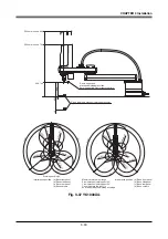
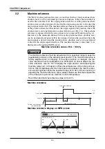
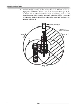
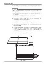
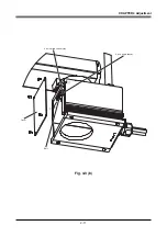
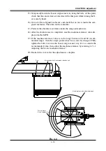
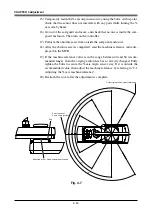
6) Check that the absolute reset axis must be positioned at the plus side of the
origin. (See Fig. 4-2.) If it is not at the plus side, then press the jog key to
move the target axis to the plus side.
7) Since the message "Reset ABS encoder OK?" is displayed, check that there
are not any obstacles in the robot movement range, and press the F4 key
(YES).
Summary of Contents for YK-X Series
Page 1: ...User s Manual ENGLISH E YAMAHA SCARA ROBOT E35 Ver 1 08 YK XG YK X series ...
Page 2: ......
Page 6: ...MEMO ...
Page 10: ...MEMO ...
Page 12: ...MEMO ...
Page 30: ...MEMO ...
Page 36: ...MEMO ...
Page 46: ...3 10 CHAPTER 3 Installation Ground symbol M4 Ground terminal Fig 3 6 Ground terminal ...
Page 78: ...3 42 MEMO ...
Page 80: ...MEMO ...
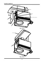
Page 101: ...4 21 CHAPTER 4 Adjustment Cover Elongated hole Y axis origin sensor stay Bolt Fig 4 8 a ...
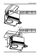
Page 102: ...4 22 CHAPTER 4 Adjustment Dog Hex nut Fig 4 8 b Bolt Y axis arm X axis arm Fig 4 8 c ...
Page 119: ...4 39 CHAPTER 4 Adjustment R End effector End effector Z Y X Fig 4 18 ...
Page 120: ...4 40 MEMO ...
Page 122: ...MEMO ...
Page 138: ...5 16 CHAPTER 5 Periodic Inspection M6 16 M5 16 X axis motor Base Fig 5 3 ...
Page 146: ...5 24 CHAPTER 5 Periodic Inspection M3 16 M4 18 X axis arm Fig 5 10 ...
Page 155: ...5 33 CHAPTER 5 Periodic Inspection O ring r M5 14 M6 16 R axis motor Fig 5 17 ...
Page 156: ...5 34 CHAPTER 5 Periodic Inspection M3 14 M3 16 O ring w Fig 5 18 ...
Page 161: ...CHAPTER 6 Increasing the robot operating speed 1 Increasing the robot operating speed 6 1 ...
Page 162: ...MEMO ...
Page 168: ...6 6 MEMO ...
Page 170: ...MEMO ...
Page 177: ...MEMO ...


