


4-19
CHAPTER 4 Adjustment
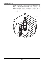
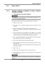
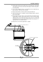
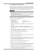
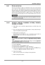
2-2 Changing the Y-axis origin position
The Y-axis origin position can be changed to any position in the range from the
front position of the Y-axis arm and X-axis arm to a maximum of 120
°
clockwise
and counterclockwise at 30
°
intervals, by changing the positions of the dog and
the mounting bolt for the Y-axis speed reduction unit as shown in Fig. 4-7.
!
CAUTION
• If the origin position has been changed, then the absolute reset must be
performed, the machine reference must be adjusted, and the standard coor-
dinate and point data must be reset.
• The dog and bolt might come off and cause the joint to lock up unless you
apply "Screw Lock" to them and tighten to the specified torque.
The following describes the method for changing the Y-axis origin position, for
example, to a position 90
°
counterclockwise.
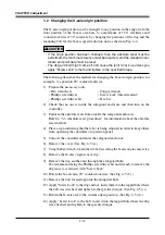
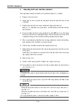
1) Prepare the necessary tools.
• Hex wrench set
• Torque wrench
• Phillips screwdriver
• Screw Lock (thread sealant)
• Phillips screwdriver bit
• Hex bit
2) Check that no one is inside the safeguard enclosure and then turn on the
controller.
3) Perform the absolute reset from outside the safeguard enclosure.
Refer to "3-3 Absolute reset procedures" for information about the absolute
reset method.
4) Place a sign indicating that the robot is being adjusted in order to keep others
from operating the controller or operation panel.
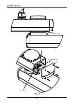
5) Turn off the controller and enter the safeguard enclosure.
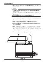
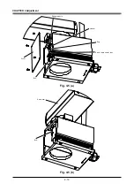
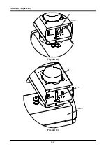
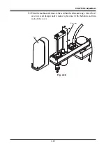
6) Remove the cover. (See Fig. 4-8 (a).)
7) Using the hex wrench, loosen the two bolts securing the Y-axis origin sensor stay.
8) Remove the Y-axis origin sensor stay.
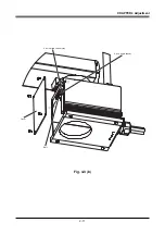
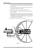
9) Remove the dog and hex nut through the elongated hole. (See Fig. 4-8 (b).)
We recommend using the Phillips screwdriver bit and wrench to remove the
dog since it is secured with "Screw Lock".
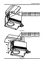
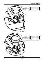
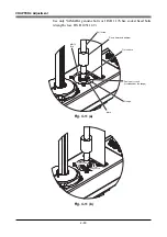
10) Rotate the Y-axis arm 90
°
counterclockwise. (See Fig. 4-8 (c).)
11) Remove the bolt located opposite the elongated hole.
12) Apply "Screw Lock" to the dog and nut, insert them into the tapped hole where
the bolt was attached, and tighten to the specified torque. (See Fig. 4-8 (d).)
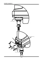
13) Return the Y-axis arm to the current origin position. (See Fig. 4-8 (e).)
14) Apply "Screw Lock" to the bolt, insert it into the tapped hole where the dog
was attached, and tighten to the specified torque.
Summary of Contents for YK-X Series
Page 1: ...User s Manual ENGLISH E YAMAHA SCARA ROBOT E35 Ver 1 08 YK XG YK X series ...
Page 2: ......
Page 6: ...MEMO ...
Page 10: ...MEMO ...
Page 12: ...MEMO ...
Page 30: ...MEMO ...
Page 36: ...MEMO ...
Page 46: ...3 10 CHAPTER 3 Installation Ground symbol M4 Ground terminal Fig 3 6 Ground terminal ...
Page 78: ...3 42 MEMO ...
Page 80: ...MEMO ...
Page 101: ...4 21 CHAPTER 4 Adjustment Cover Elongated hole Y axis origin sensor stay Bolt Fig 4 8 a ...
Page 102: ...4 22 CHAPTER 4 Adjustment Dog Hex nut Fig 4 8 b Bolt Y axis arm X axis arm Fig 4 8 c ...
Page 119: ...4 39 CHAPTER 4 Adjustment R End effector End effector Z Y X Fig 4 18 ...
Page 120: ...4 40 MEMO ...
Page 122: ...MEMO ...
Page 138: ...5 16 CHAPTER 5 Periodic Inspection M6 16 M5 16 X axis motor Base Fig 5 3 ...
Page 146: ...5 24 CHAPTER 5 Periodic Inspection M3 16 M4 18 X axis arm Fig 5 10 ...
Page 155: ...5 33 CHAPTER 5 Periodic Inspection O ring r M5 14 M6 16 R axis motor Fig 5 17 ...
Page 156: ...5 34 CHAPTER 5 Periodic Inspection M3 14 M3 16 O ring w Fig 5 18 ...
Page 161: ...CHAPTER 6 Increasing the robot operating speed 1 Increasing the robot operating speed 6 1 ...
Page 162: ...MEMO ...
Page 168: ...6 6 MEMO ...
Page 170: ...MEMO ...
Page 177: ...MEMO ...


