background image

YST-SW015

IMPORTANT NOTICE

This manual has been provided for the use of authorized YAMAHA
Retailers and their service personnel.
It has been assumed that basic service procedures inherent to the industry,
and more specifically YAMAHA Products, are already known and
understood by the users, and have therefore not been restated.

WARNING:

Failure to follow appropriate service and safety
procedures when servicing this product may result in
personal injury, destruction of expensive components,
and failure of the product to perform as specified.  For
these reasons, we advise all YAMAHA product owners
that any service required should be performed by an
authorized YAMAHA Retailer or the appointed service
representative.

IMPORTANT:

The presentation or sale of this manual to any individual
or firm does not constitute authorization, certification or
recognition of any applicable technical capabilities, or
establish a principle-agent relationship of any form.

The data provided is believed to be accurate and applicable to the unit(s)
indicated on the cover.  The research, engineering, and service departments
of YAMAHA are continually striving to improve YAMAHA products.
Modifications are, therefore, inevitable and specifications are subject to
change without notice or obligation to retrofit.  Should any discrepancy
appear to exist, please contact the distributor's Service Division.

WARNING:

Static discharges can destroy expensive components.
Discharge any static electricity your body may have
accumulated by grounding yourself to the ground buss in
the unit (heavy gauge black wires connect to this buss).

IMPORTANT:

Turn the unit OFF during disassembly and part
replacement.  Recheck all work before you apply power
to the unit.

CONTENTS

TO SERVICE PERSONNEL .......................................... 2
SPECIFICATIONS / 

参考仕様

........................................ 2

INTERNAL VIEW ........................................................... 3
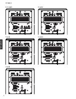
REAR PANELS .......................................................... 3~4
DISASSEMBLY PROCEDURES

 / 分解手順

............. 5~6

CONFIRMATION OF AUTO STANDBY OPERATION /

AUTO STANDBY動作確認 .............................................

7

BLOCK DIAGRAM ......................................................... 8
PRINTED CIRCUIT BOARD .................................... 9~10
SCHEMATIC DIAGRAM .............................................. 11
PARTS LIST ........................................................... 13~19
Parts List for Carbon Resistors ................................ 20

1 0 0 8 3 5

P.O.Box 1, Hamamatsu, Japan

SERVICE  MANUAL

SUBWOOFER SYSTEM

YST-SW015

Summary of Contents for YST-SW015

Page 1: ...any form The data provided is believed to be accurate and applicable to the unit s indicated on the cover The research engineering and service departments of YAMAHA are continually striving to improve YAMAHA products Modifications are therefore inevitable and specifications are subject to change without notice or obligation to retrofit Should any discrepancy appear to exist please contact the dist...

Page 2: ...0 x 325 x 320 mm 11 x 12 13 16 x 12 5 8 Weight 質量 9 2 kg 20 lbs 5 oz Finish Cherry Color All models Black Color All models Silver Color All models Accessories 付属品 Subwoofer Cable 3 m x 1 pc J model Non skid Pad x 4 pcs Specifications are subject to change without notice due to product improvements 参考仕様および外観は予告なく変更されることがあります U U S A model C Canadian model A Australian model B British model G Europe...

Page 3: ...MAIN 8 P C B 2 MAIN 4 P C B 3 MAIN 3 P C B 4 MAIN 1 P C B 5 MAIN 9 P C B R T K models 6 MAIN 2 P C B 7 MAIN 5 P C B 8 MAIN 7 P C B U C A B G J models MAIN 10 P C B R T K models 9 MAIN 6 P C B REAR PANELS A model U C models 7 8 9 1 2 3 4 6 5 ...

Page 4: ...YST SW015 4 YST SW015 B G models T model J model K model R model ...

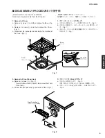
Page 5: ...ews 1 and then remove the Base Fig 1 b Remove 4 screws 2 and then remove the Driver Fig 1 c Disconnect the connector connected to the terminal of the Driver Fig 1 Fig 2 Fig 1 2 フロントパネルAss yの外し方 a のネジ4本を外します Fig 2 取り外しには六角レンチ 2 5mm を使用します b フロントパネルAss yを引き出し CB4を外します Fig 2 2 Removal of Front Panel Ass y a Remove 4 screws 3 Fig 2 Use an Allen wrench 2 5mm to unscrew the Front Panel Ass y b Pull out ...

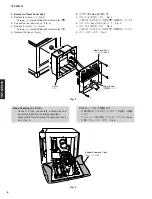
Page 6: ...he rear panel ass y Fig 3 a Remove 2 screws 5 Fig 3 Screws 5 are identified with arrow marks b Remove the cover Fig 3 When Checking the P C B Connect all the connectors removed during disassembly back to the original positions Spread cloth first and place the rear panel ass y on it Fig 4 P C B チェックをする場合には 分解の際に外したコネクターをすべて元通りに接続 します ゴムシートと布を敷き その上にリアパネルAss y を置いてチェックします Fig 4 Fig 4 Rear Panel Ass ...

Page 7: ...n the MAIN P C B 3 3 Connect the output signal from the signal generator to the INPUT of the unit 4 Set the signal generator for the sine wave of 100Hz 8mV 5 Turn on the power switch located on the rear panel Confirmation 1 Set the AUTO STANDBY switch to the LOW position 2 Turn on the STANDBY ON switch The display LED lights up green and its color changes to red after 5 to 10 seconds 3 Turn off th...

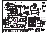
Page 8: ... 4 3 IC7B IC7A L P F 12dB oct 8 6 7 VR1 VOLUME VR2 HIGH CUT 7 6 5 IC1B IC1A 1 2 3 MUSIC SENSOR IC4 TIMER IC5 8 4 6 7 3 AUTO STANDBY SW2 H AUTO POWER ON OFF CIRCUIT Q5 6 7 8 D4 5 22 23 INPUT L R Q12 R60 C46 POWER AMP 1 H P F 12dB oct OFF L IC9 REGULATOR Q4 13 D14 REGULATOR R T K models only POWER SW5 A N I C IC2 Q16 L P F 6dB oct 1 10 L P F 6dB oct PHASE REVERSE NORMAL Q14 15 ...

Page 9: ...W HIGH REV NORM CONFIRMATION OF AUTO STANDBY OPERATION R60 1MΩ PRINTED CIRCUIT BOARD Foil side Ref No Location D1 E3 D2 E4 D3 E4 D4 A3 D5 B3 D6 C2 D7 B3 D9 C4 D10 G4 D11 H4 D14 H4 D19 C3 D20 C3 D21 C3 D22 A3 D23 B3 IC1 C6 IC2 C3 IC3 D4 IC4 E6 IC5 E7 IC8 C2 IC9 G4 Q1 B3 Q2 B3 Q4 G4 Q5 A3 Q6 B3 Q7 A3 Q8 B3 Q9 E4 Q10 E4 Q11 G4 Q12 E6 Q13 G4 Q14 C4 Q15 C4 Q16 B3 Semiconductor Location Circuit No J U C...

Page 10: ...S MAIN LEDR E LEDG LEDR E LEDG 9 1 MAIN 2 Power Transformer W11B W5B W8B W9B MAIN 2 W8B W9B W15B W13B W16B W14B W13A W14A W15A W16A W12B MAIN 6 P C B R T K models Lead Type Device MAIN 1 Power Transformer W5B 110 120V 220 240V ON STANDBY MUSIC MOVIE PRINTED CIRCUIT BOARD Foil side Semiconductor Location Circuit No J U C R T K A B G C40 O O X O O C53 X X X X O C62 63 X X O X X CB7 8 X X O X X D14 X...

Page 11: ...ive circuit IC5 LB8555D Timer 1 VCC 8 DISCHARGE 7 CONTROL VOLTAGE 5 THRESHOLD 6 TRIGGER GND 2 RESET 4 R S Q 1 4 8 OUTPUT 3 IC8 STK404 070 AF Power Amp 1 3 2 4 5 6 7 8 9 10 R1 R4 R5 C1 C2 D1 TR3 TR5 R3 R6 TR4 SUB R2 TR1 TR2 TR6 TR7 TR8 1 10 VIN VOUT GND OUT COM IN IC9 NJM78L08A Voltage Regulator PIN CONNECTION DIAGRAM OF TRANSISTORS DIODES AND ICS 2SB1642 2SD2531 2SK304 2SC4688 1SS133 MTZJ12 0C MTZ...

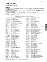
Page 12: ...E DIODE ZENR ZENER DIODE DSCR CE CERAMIC DISCRIMINATOR FER BEAD FERRITE BEADS FER CORE FERRITE CORE FET CHP CHIP FET FL DSPLY FLUORESCENT DISPLAY FLTR CE CERAMIC FILTER FLTR COMB COMB FILTER MODULE FLTR LC RF LC FILTER EMI GND MTL GROUND PLATE GND TERM GROUND TERMINAL HOLDER FUS FUSE HOLDER IC PRTCT IC PROTECTOR JUMPER CN JUMPER CONNECTOR JUMPER TST JUMPER TEST POINT L DTCT LIGHT DETECTING MODULE ...

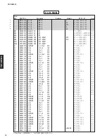
Page 13: ...R867100 C EL 10uF 50V ケミコン 01 C12 UR867470 C EL 47uF 50V ケミコン 01 C13 UA655100 C MYLAR 0 1uF 50V マイラーコン 01 C14 UR868100 C EL 100uF 50V ケミコン 01 C15 UR838100 C EL 100uF 16V ケミコン 01 C16 FG652100 C CE 100pF 50V セラコン 01 C17 UA655150 C MYLAR 0 15uF 50V マイラーコン 01 C18 UA654680 C MYLAR 0 068uF 50V マイラーコン 02 C19 FG652100 C CE 100pF 50V セラコン 01 C20 UR837470 C EL 47uF 16V ケミコン 01 C21 UR837470 C EL 47uF 16V ケミコ...

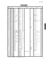
Page 14: ...01 C65 FG644220 C CE 0 022uF 50V セラコン 01 s D1 VN011300 DIODE BRG D3SBA20 4A 200V ダイオード 03 D2 VG440900 DIODE ZENR MTZJ15C 15V ツェナーダイオード 01 D3 VG440900 DIODE ZENR MTZJ15C 15V ツェナーダイオード 01 D4 VD631600 DIODE 1SS133 176 ダイオード 01 D5 VD631600 DIODE 1SS133 176 ダイオード 01 D6 VD631600 DIODE 1SS133 176 ダイオード 01 D7 VG442500 DIODE ZENR MTZJ24B 24V ツェナーダイオード 01 D9 VD631600 DIODE 1SS133 176 ダイオード 01 D10 VD631600 D...

Page 15: ... 4W 金属被膜抵抗 R36 HB027100 R MTL FLM 10KΩ 1 4W 金属被膜抵抗 R39 VC760500 R MTL OXD 470Ω 2W 酸化金属被膜抵抗 01 R45 HV755150 R CAR FP 150Ω 1 4W 不燃化カーボン抵抗 01 R46 HV755150 R CAR FP 150Ω 1 4W 不燃化カーボン抵抗 01 R47 VC751900 R MTL OXD 0 22Ω 2W 酸化金属被膜抵抗 02 R48 HV754100 R CAR FP 10Ω 1 4W 不燃化カーボン抵抗 01 R62 HV753220 R CAR FP 2 2Ω 1 4W JUCABG 不燃化カーボン抵抗 01 R66 HB026270 R MTL FLM 2 7KΩ 1 4W 金属被膜抵抗 01 R67 HB028100 R MTL FLM 100KΩ 1 4...

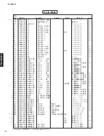
Page 16: ...N Schm Ref PART NO Description Remarks Markets 部 品 名 Rank New Parts 新規部品 マーク の部品は 基板に含まれません VR1 WA113000 VR A 5KΩ VOLUME ロータリーVR VR2 WA112800 VR SC 10KΩ HIGH CUT ロータリーVR V5995800 PLATE GND アースプレート V7572400 HOLDER LED LE56209 0 LEDホルダー ...

Page 17: ...6 4 32 4 31 4 37 4 32 4 32 4 32 4 33 7 10 4 1 4 11 6 4 1 1 201 202 EXPLODED VIEW 1 3 3 はSW3とSW4に接着されているため部品 交換の場合 3 3 2個とSW3およびSW4を同 時に交換しなければなりません また部品交換の後 3 3 を必ずSW3とSW4に 接着してください 推奨接着剤 Diabond 1620B 1 The part marked 3 3 is bonded to SW3 and SW4 Therefore for the part replacement two pieces of 3 3 SW3 and SW4 must be replaced simultaneously Also after replacement 3 3 must be bonded to SW3 and S...

Page 18: ...689600 POWER CABLE 2m UC 電源コード 05 s 4 3 WA507100 POWER CABLE 2m R 電源コード s 4 3 VZ555600 POWER CABLE 2m T 電源コード 05 s 4 3 V8012900 POWER CABLE 2m K 電源コード s 4 3 V6792800 POWER CABLE 2m A 電源コード s 4 3 V6977100 POWER CABLE 2m B 電源コード s 4 3 V6893100 POWER CABLE 2m G 電源コード 4 4 CB072750 CORD STOPPER SR 4N 4 コードストッパー 01 4 5 CB069250 BINDING TIE BK 1 束線止め 01 4 11 WA107700 REAR PANEL J リアパネル 4 11 WA201000 REAR...

Page 19: ... 1 0 Ω HJ35 3100 HF85 3100 1 8 Ω HJ35 3180 2 2 Ω HJ35 3220 HF85 3220 3 3 Ω HJ35 3330 HF85 3330 4 7 Ω HJ35 3470 HF85 3470 5 6 Ω HJ35 3560 HF85 3560 10 Ω HF45 4100 HF45 4100 15 Ω HJ35 4150 HF85 4150 22 Ω HF45 4220 HF45 4220 27 Ω HJ35 4270 HF85 4270 33 Ω HF45 4330 HF45 4330 39 Ω HJ35 4470 HF85 4390 47 Ω HF45 4470 HF45 4470 56 Ω HF45 4560 HF45 4560 68 Ω HF45 4680 HF45 4680 75 Ω HF45 4750 HF45 4750 82 ...

Reviews: