YST-SW015
6
YST-SW015
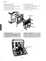
Fig. 3
3. リアパネルAss'yの外し方
a. ④のネジ8本を外します。(Fig. 3)
※ 取り外す④のネジには矢印
(
)
が印刷されています。
b. リアパネルAss'yを引き出します。(Fig. 3)
c. ⑤のネジ2本を外します。(Fig. 3)
※ 取り外す⑤のネジには矢印
(
)
が印刷されています。
d. カバーを外します。(Fig. 3)
3. Removal of Rear Panel Ass'y
a. Remove 8 screws (
4
). (Fig. 3)
* Screws (
4
) are identified with arrow marks (
).
b. Pull out the rear panel ass'y. (Fig. 3)
a. Remove 2 screws (
5
). (Fig. 3)
* Screws (
5
) are identified with arrow marks (
).
b. Remove the cover. (Fig. 3)
When Checking the P.C.B.:
• Connect all the connectors removed during
disassembly back to the original positions.
• Spread cloth first and place the rear panel ass'y
on it. (Fig. 4)
P.C.B.チェックをする場合には
・ 分解の際に外したコネクターをすべて元通りに接続
します。
・ ゴムシートと布を敷き、その上にリアパネルAss'y
を置いてチェックします。(Fig. 4)
Fig. 4
Rear Panel Ass'y
リヤパネル Ass'y
Power Switch
主電源スイッチ
Cover
カバー
4
5
5
4
Rubber Sheet and Cloth
ゴムシートと布


