background image

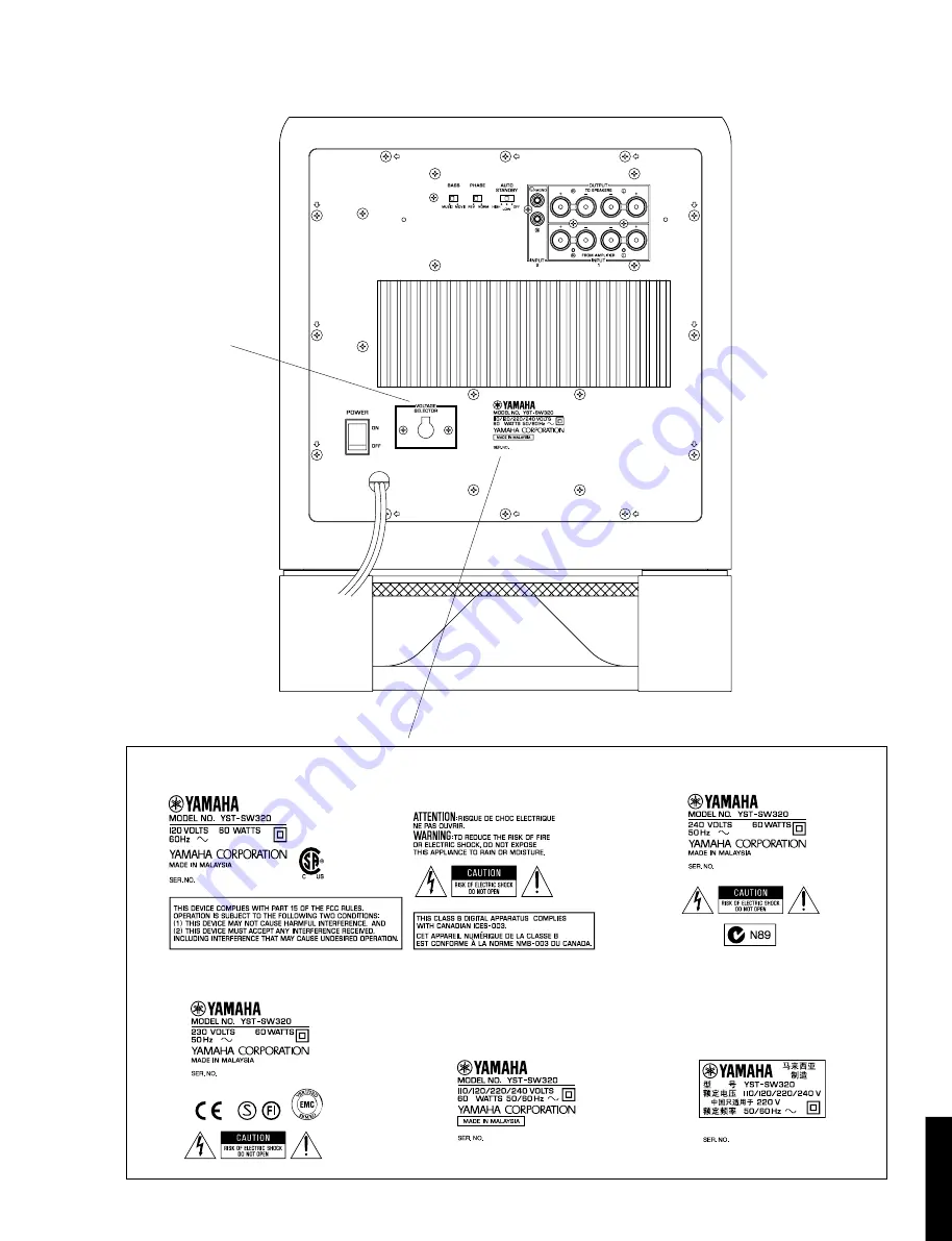
YST-SW320

YST-SW320

 REAR PANEL

▼ 

U, C models

▼ 

A model

▼ 

B, G models

▼ 

R model

▼ 

T model

2

R, T models only

Summary of Contents for YST-SW320

Page 1: ...rvice representative IMPORTANT The presentation or sale of this manual to any individual or firm does not constitute authorization certification or recognition of any applicable technical capabilities or establish a principle agent relationship of any form The data provided is believed to be accurate and applicable to the unit s indicated on the cover The research engineering and service departmen...

Page 2: ...DER ELECTRICAL ELECTRONIC OR PLASTIC COMPONENTS IN YOUR MOUTH FOR ANY REASON WHATSOEVER Avoid prolonged unprotected contact between solder and your skin When soldering do not inhale solder fumes or expose eyes to solder flux vapor If you come in contact with solder or components located inside the enclosure of this product wash your hands before handling food 1 Leakage current must not exceed 0 5m...

Page 3: ...YST SW320 YST SW320 REAR PANEL U C models A model B G models R model T model 2 R T models only ...

Page 4: ...crews w and then remove the Base Ass y in Fig 2 b Remove 4 screws e and then remove the Loud Speaker in Fig 2 3 Removal of Rear Panel Ass y Remove 12 screws r in Fig 3 Arrow marks are printed to identify the screws to be removed Installation of emblem 1 Put the emblem into the cabinet at the specified posi tion 2 Place a piece of cloth wood on top of the emblem 3 Using a mallet hammer the emblem i...

Page 5: ...wer switch As shown in Fig A apply rapid cures bond such as 5 minute epoxy to the power switch the area which contacts the rear panel insert it in the rear panel and make sure it is fixed Inserting the power switch in the rear panel only would not be sufficient for its secure installation Precaution for installation of power cord After connecting the power cord be sure to apply the rapid cures bon...

Page 6: ...onnect it to the load resistor 3 Connect the HOT side of the oscilloscope CH1 probe to the point A or B indicated in the figure and the GND side to the GND of the main unit 4 Connect the oscilloscope CH2 input to the red side of the connector cable which is connected with the load resistor At this time the GND terminal of CH2 must be left unconnected Setting 1 Set the signal generator to the sine ...

Page 7: ...YST SW320 YST SW320 6 IDLING CURRENT ADJ DC 50mV to 250mV A B RE WH Main 1 P C B DC 50mV to 250mV TP11 TP12 VR1 D30 D29 Point A Point B Schematic Diagram Test Points ...

Page 8: ...NTED CIRCUIT BOARD Foil side 7 8 1 FROM MAIN 2 RE WH W19 W20 TO SPEAKER V1 AYST DR OUT DR B1 E B1 RE BL RE W7 W6 W5 TO MAIN 6 FROM MAIN 2 IDLING CURRENT ADJ Q16C Q1C Q9 Q1A Q17C Q17A Q16A MAIN 1 P C B A B DC 50mV to 250mV IDLING TEST POINT ...

Page 9: ...CUIT BOARD Foil side 8 9 1 9 1 BE BL BE W16 W15 W14 TO MAIN 6 TO MAIN 1 DR OUT DR AYST V1 17 W17 TO MAIN 3 VCC VCC E E PWS V1 2 W2 FROM MAIN 4 MA1 E TOVL 12 12 LIM MA2 FROM MAIN 5 TVOL E MAIN V2 12 12 PWS VCC B1 E B1 18 W18 TO MAIN 1 MAIN 2 P C B ...

Page 10: ...oil side 9 8 9 1 1 MAIN 3 P C B MAIN 7 P C B FROM MAIN 2 V1 PWS E E VCC VCC FROM MAIN 4 SWL SWH2 SWH1 SO R T models W11 GR W10 BR TO VOLTAGE SELECTOR OR W12 GY W13 TO MAIN 8 W9 BE GY BL OR WH BE RE W8 RE TO POWER CORD TO POWER TRANSFORMER TO VOLTAGE SELECTOR ...

Page 11: ...ST SW320 PRINTED CIRCUIT BOARD Foil side 10 8 1 9 1 MAIN 3 P C B MAIN 7 P C B OR W12 BE W9 WH W8 GY W13 TO MAIN 8 FROM POWER CORD TO POWER TRANSFORMER FROM MAIN 2 V1 PWS E E VCC VCC FROM MAIN 4 SWL SWH2 SWH1 SO U C A B G models ...

Page 12: ...UTO STANDBY INPUT 2 R L OUTPUT INPUT 1 MA2 LIM 12 12 TOVL E MA1 TO MAIN 2 1 W1 SWL SWH2 SWH1 SO TO MAIN 3 4 W4 MAIN 4 P C B R T B G ONLY 9 1 FROM MAIN 2 TOVL E MAIN V2 12 12 PWS VCC VOLUME HIGH CUT SATNDBY ON MAIN 5 P C B 11 PRINTED CIRCUIT BOARD Foil side ...

Page 13: ...B C D E 1 2 3 4 5 6 7 YST SW320 W7 W6 W5 W14 W15 W16 FROM POWER TRANSFORMER RE BL RE BE BL BE TO MAIN 2 TO MAIN 1 MAIN 6 P C B W12 W13 OR GY TO MAIN 3 MAIN 8 P C B POWER 12 PRINTED CIRCUIT BOARD Foil side ...

Page 14: ...2 PWR REGULATOR IC12 Q11 L R INPUT 1 L R INPUT 2 L R OUTPUT IC1A 4 3 2 SW2 PHASE SELECT IC1B L P F 12dB oct 6 8 BASS SELECT SW4 PRE DRIVE Q2 8 10 POWER DRIVE Q9 16A C 26A C Q28 29 A N I C LIMITER RY1 IC8 9 Q25 D12 13 19 Q18 21 D6 14 33 34 0 1 SPEAKER Q1C 17C 24A Q27 31 PS AMP Q1A 17A 24C Q30 32 PS AMP B B H P F 12dB oct 12 12 REGULATOR POWER SUPPLY D2 IC6 IC10 F1 POWER SW5 B B POWER SUPPLY D1 STAN...

Page 15: ... 11 5 0 9 0 0 7 11 5 0 7 9 0 3 9 7 9 6 7 0 3 9 6 6 1 3 0 0 7 5 0 1 3 6 6 7 9 5 3 7 5 7 5 7 9 0 0 16 4 16 4 0 16 4 11 8 0 16 4 11 9 6 6 6 0 0 0 0 11 8 0 0 0 3 0 3 11 9 0 0 0 0 11 9 0 0 0 0 11 8 0 0 1 5 0 0 0 0 0 1 0 1 0 1 11 9 11 8 0 0 0 0 0 0 62 5 61 9 61 8 61 9 62 5 61 4 61 8 61 4 1 6 61 4 61 8 61 8 0 0 2 0 7 0 7 61 6 62 1 62 9 62 4 61 6 61 6 62 1 1 7 1 0 1 6 1 7 1 7 1 1 4 2 63 1 63 1 3 6 1 1 3 6...

Page 16: ...ITTING MODULE LED DSPLY LED DISPLAY LED INFRD LED INFRARED MODUL RF MODULATOR RF PHOT CPL PHOTO COUPLER PHOT INTR PHOTO INTERRUPTER PHOT RFLCT PHOTO REFLECTOR PIN TEST PIN TEST POINT PLST RIVET PLASTIC RIVET R ARRAY RESISTOR ARRAY R CAR CARBON RESISTOR R CAR CHP CHIP RESISTOR R CAR FP FLAME PROOF CARBON RESISTOR R FUS FUSABLE RESISTOR R MTL CHP CHIP METAL FILM RESISTOR R MTL FLM METAL FILM RESISTO...

Page 17: ... C35 V5058000 C MYLAR 4 7uF 250V C36 V5058000 C MYLAR 4 7uF 250V C37 UA654470 C MYLAR 0 047uF 50V C38 FG251220 C CE 22pF 50V C39 FG212120 C CE 120pF 50V C40 VF606700 C EL 1000uF 25V BG C40 VF606700 C EL 1000uF 25V UCABG C40 VH620500 C EL 10uF 25V RT C41 UA654470 C MYLAR 0 047uF 50V C42 FG214100 C CE 0 01uF 50V C43 FG213100 C CE 1000pF 50V C44 VJ839100 C EL 1uF 50V C45 UA654680 C MYLAR 0 068uF 50V ...

Page 18: ...CK PIN 2P RJ 1060 01 0500 Q1 iX632610 TR A1837 C4793 O Y Q2 iC1815M0 TR 2SC1815 Y GR Q3 iA097000 TR 2SA970 GR BL Q4 iA097000 TR 2SA970 GR BL Q5 iC1815M0 TR 2SC1815 Y GR Q6 iA101590 TR 2SA1015 O Y Q7 iA097000 TR 2SA970 GR BL Q8 VE198700 TR 2SA1145 O Y Q9 VC398100 TR 2SC1846 S Q10 VE198800 TR 2SC2705 O Y Q11 iC224030 TR 2SC2240 GR BL Q12 iC224030 TR 2SC2240 GR BL Q13 iC224030 TR 2SC2240 GR BL RT Q14...

Page 19: ...20 R CAR FP 22Ω 1 4W R125 HV453220 R CAR FP 2 2Ω 1 4W R128 HV453470 R CAR FP 4 7Ω 1 4W R129 HV453470 R CAR FP 4 7Ω 1 4W R130 HV453470 R CAR FP 4 7Ω 1 4W R132 HV453220 R CAR FP 2 2Ω 1 4W R135 HV455560 R CAR FP 560Ω 1 4W R152 HV455470 R CAR FP 470Ω 1 4W Z RY1 VU161600 RELAY DC OSA SS 224DM3 Z RY2 VU349800 RELAY DC SDT SS 112DM ST1 BB071360 SCR TERM 8 3x13 SW1 VS066500 SW PUSH SPPH13 W SW2 V5178000 S...

Page 20: ...1 4 6 4 15 5 24 5 34 5 34 5 12 1 8 5 17 5 18 5 18 5 11 5 37 5 37 5 33 5 19 1 7 5 14 5 8 5 6 5 15 5 16 5 20 5 36 5 5 5 21 5 22 5 31 5 32 5 31 5 17 5 31 5 35 5 34 5 34 35 32 32 27 2 35 27 27 35 35 12 1 12 10 12 1 12 10 12 10 12 1 12 10 4 15 5 23 5 11 5 38 1 12 1 12 1 12 1 12 1 12 1 12 4 12 11 1 4 11 1 11 5 31 11 2 11 10 11 10 11 10 11 10 R T models 3 8 5 1 4 2 5 1 1 6 5 1 1 1 Accessories ...

Page 21: ...FC2 5 1 12 Ei330086 BIND HEAD B TITE SCREW 3x8 FCRM3 BL 5 1 13 VK173200 SCREW TRANSISTOR 3x15 SP FCM3 Z 5 5 XY291B00 POWER TRANSFORMER A Z 5 5 XY292B00 POWER TRANSFORMER BG Z 5 5 XY290B00 POWER TRANSFORMER RT Z 5 5 XY289B00 POWER TRANSFORMER UC Z 5 6 V3756200 POWER CORD 10A SPT 2 2 1m UC Z 5 6 VQ790000 POWER CORD 5A 2 0m B Z 5 6 VT666200 POWER CORD ASS Y A Z 5 6 VZ555600 POWER CORD 10A 250V 2 0m R...

Page 22: ...IND HEAD P TITE SCREW 4x12 MFC2 BL 5 38 ED330086 BIND HEAD SCREW 3x8 FCRM3 BL RT 11 1 V5858600 BASE 11 2 V5836700 REFLECTOR 11 10 V5858900 FLAT HEAD TAPPING SCREW 1 4 0x14 12 1 V5859900 LEG 12 10 03763040 FLANGE NUT D 6 0X13 MFZN2Y 21 VS755300 BUSH B 26 V2729700 EMBLEM A 27 V5881400 SPACER 32 Ei340256 BIND HEAD TAPPING SCREW 4x25 ZMC2 BL 33 V6018100 HEXAGON SOCKET TAPPING SCREW 4x16 MFCR33 34 VB13...

Page 23: ... 4100 HF85 4150 HF45 4220 HF85 4270 HF45 4330 HF85 4390 HF45 4470 HF45 4560 HF45 4680 HF45 4750 HF45 4820 HF45 4910 HF45 5100 HF85 5110 HF45 5120 HF45 5150 HF45 5180 HF45 5200 HF45 5220 HF45 5270 HF45 5330 HF45 5390 HF45 5430 HF45 5470 HF45 5510 HF45 5560 HF45 5680 HF45 5820 HF45 5910 HF45 6100 HF45 6120 HF45 6150 HF45 6180 HF85 6200 HF45 6220 HF85 6240 HF45 6270 HF45 6300 HF45 6330 HF85 6360 HF45...

Reviews: