background image

– 13 –

CONTROL FUNCTION

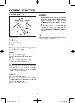
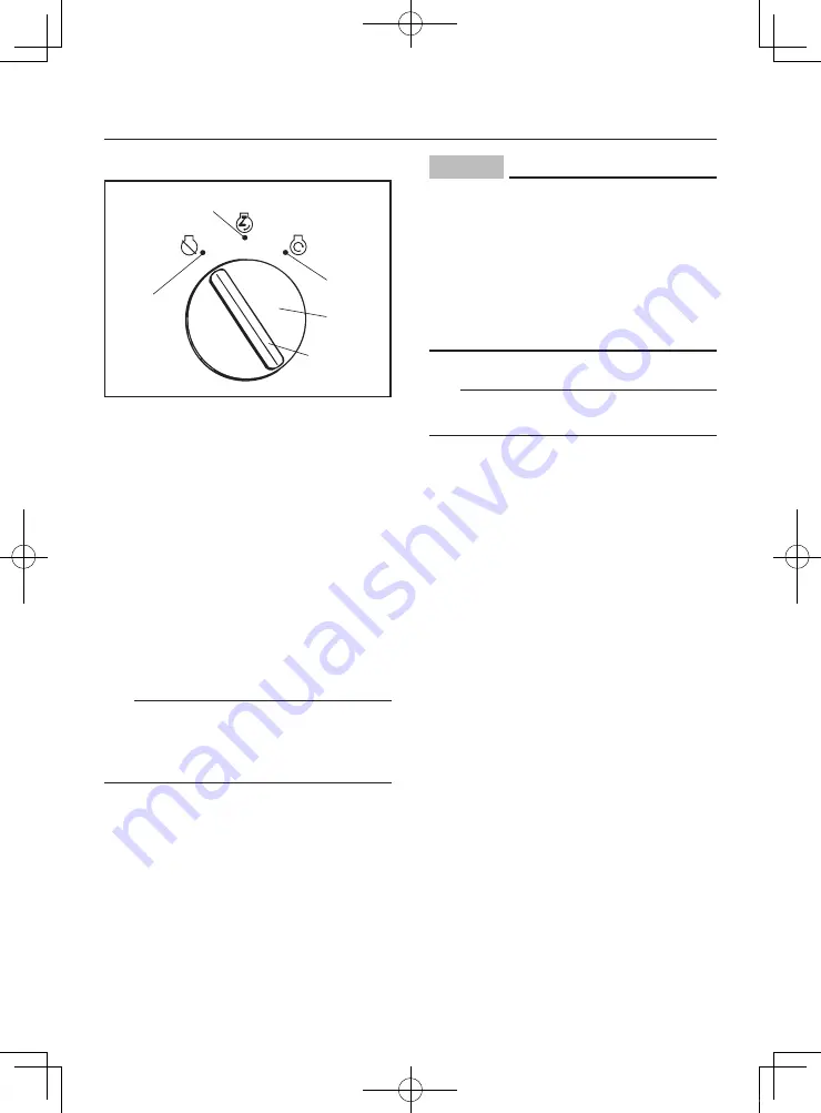
ENGINE SWITCH

1

2

3

5

4

STOP

ON

START

1. “STOP 

5

2. “ON 

7

3. “START 

6

4.  Engine switch key
5. Grip

The engine switch controls the ignition and 
the starter motor system.

STOP 

5

:

Position to stop the engine.
The key can be inserted or removed.

ON 

7

:

Position when the engine is running.
The key cannot be removed.

TIP

The working light automatically comes on 
when the engine switch is turned to “ON 

7

”. 

The working light turns off when the engine 
switch is turned to “STOP


5

”.

START 

6

:

Position to start the engine.
The starter motor cranks the engine. When 
releasing the grip, the key returns to the “ON 

7

” position automatically.

The key cannot be removed.

NOTICE


9

 Do not continue to use the starter 

motor for more than 5 seconds. Do-
ing so will consume a large amount 
of power and it may exhaust the bat-
tery.


9

 Do not leave the key in the “ON 

7

” 

position for a long time while the en-
gine is stopped. It may exhaust the 
battery.

TIP

Remove the engine switch key when you 
are not using the Snowblower.

7T0-28199-70-E0.indd   13

2019/05/01   9:22:55

Summary of Contents for YT624

Page 1: ...Read this manual carefully before operating this machine 7T0 28199 70 YT624 Snowblower OWNER S MANUAL 7T0 28199 70_cover indd 1 2019 05 01 9 24 35 ...

Page 2: ...7T0 28199 70_cover indd 2 2019 05 01 9 24 35 ...

Page 3: ...trations and text shown in this manual may differ from the actual model due to changes in specifications or other reasons Take care of this manual Please attach this manual to the product when it is lent or trans ferred to another person When depositing the product batteries oil or other components consult a Yamaha dealer for guidelines on protecting the environment All Yamaha products have warran...

Page 4: ...G THE ENGINE FOR POOR STARTING OR ABNORMAL NOISE 27 CHECKING THE EXHAUST SYSTEM 27 CHECKING THE AUGER CLUTCH AND DRIVE CLUTCH FOR OPERATION MALFUNCTION 27 CHECKING THE CHUTE OPERATION 27 CHECKING ANY TROUBLES NOTICED WHEN PREVIOUSLY OPERATING THE SNOWBLOWER 27 OPERATION 28 STARTING THE ENGINE FOR RECOIL START 28 STARTING THE ENGINE FOR ELECTRIC START 30 STOPPING THE ENGINE 32 MOVING THE SNOWBLOWER...

Page 5: ...DJUSTING THE TRACK TENSION 55 REPLACING THE SPROCKET PIN 56 BATTERY 57 REPLACING THE FUSE 59 LUBRICATING EACH PART 61 STORAGE 63 SHORT TERM 63 LONG TERM 66 SPECIFICATIONS 67 INDEX 69 7T0 28199 70 E0 indd 3 2019 05 01 9 22 50 ...

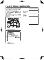
Page 6: ...er label and fill the product name and the serial number columns at right Also record the product name and product serial number separately in case of theft or emergency 1 1 Product serial number label 1 2 MADE IN JAPAN 1 Product name 2 Product serial number Product name Product serial number Date of purchase Purchased from Phone 7T0 28199 70 E0 indd 1 2019 05 01 9 22 50 ...

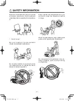
Page 7: ...tenance Do not allow children or anyone who does not understand how to operate the Snow blower correctly to operate it Never operate the Snowblower when you are tired or under the influence of alcohol or drugs Wear non slip footwear warm clothing and gloves when operating the Snowblower Do not operate the Snowblower in low vis ibility conditions such as early morning and night time 7T0 28199 70 E0...

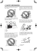
Page 8: ...equately ventilate the building even when you are moving the Snowblower Gasoline is a highly flammable and easily ignitable fuel Always turn off the engine and avoid open flame while filling the fuel tank S Remove wooden blocks cans hoses wires ropes and all other foreign objects from the location you wish to clear snow from before operating the Snowblower To clear snow on gravel make sure there i...

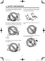
Page 9: ...ms or legs near such parts 1 2 3 1 Auger 2 Impeller 3 Chute Do not blow snow toward people buildings automobiles etc Do not fix the auger clutch lever or drive clutch lever intentionally as this will prevent the safety device to operate Do not blow snow across the face of a slope Do not use the Snowblower to clear snow on a roof or steep slope SAFETY INFORMATION 7T0 28199 70 E0 indd 4 2019 05 01 9...

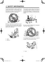
Page 10: ...shift lever in a position other than N Neutral 1 2 1 Auger 2 Shift lever The muffler exhaust pipe will still be hot immediately after the engine has stopped Place the Snowblower in a place where pe destrians are not likely to touch the Snow blower Do not use the Snowblower for purposes other than clearing snow To dislodge snow from the chute stop the engine and use the clean out tool 1 1 Chute SAF...

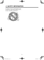
Page 11: ... 6 To attach a cover or similar device to the Snowblower wait until the engine and muf fler have completely cooled down SAFETY INFORMATION 7T0 28199 70 E0 indd 6 2019 05 01 9 22 53 ...

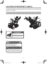
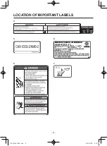
Page 12: ... safely read the labels affixed to the machine and use according to the instructions on the labels TIP If these important labels are damaged or missing contact a Yamaha dealer for replacements 1 2 6 5 4 3 7 1 2 7T0 28199 70 E0 indd 7 2019 05 01 9 22 53 ...

Page 13: ...ngine is certified to operate on unleaded gasoline ENGINE OIL TYPE No other adjustments needed Check owner s manual for further details THIS ENGINE CONFORMS TO THE SMALL OFF ROAD SPARK IGNITION ENGINE EMISSION REGULATIONS APPLICABLE TO MODEL YEAR ENGINES EM EMISSION CONTROL INFORMATION YAMAHA MOTOR CO LTD EM 7T0 28199 70 E0 indd 8 2019 05 01 9 22 54 ...

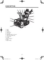
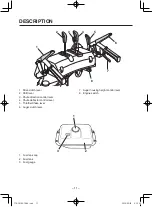
Page 14: ...l tank 4 Working light 5 Fuel gauge 6 Transmission HST oil reservoir 7 Spark plug cap Spark plug 8 Left side cover 9 Impeller 10 Shear bolt guard 11 Auger 12 Auger housing 1 2 3 4 5 6 7 8 9 10 11 12 7T0 28199 70 E0 indd 9 2019 05 01 9 22 54 ...

Page 15: ...out tool lodged snow remover 3 Right side cover 4 Scraper 5 Skid 6 Track 7 Recoil starter 8 Fuel cock 9 Air filter 10 Control panel 11 Handlebar 12 Fuel tank cap 1 2 3 4 5 6 7 8 9 10 11 12 DESCRIPTION 7T0 28199 70 E0 indd 10 2019 05 01 9 22 54 ...

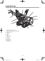
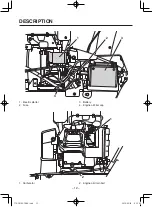
Page 16: ... direction control lever 4 Chute deflector control lever 5 Throttle Choke lever 6 Auger clutch lever 7 Auger housing height control lever 8 Engine switch 1 2 3 4 5 6 7 8 1 Fuel tank cap 2 Fuel tank 3 Fuel gauge 1 3 2 7T0 28199 70 E0 indd 11 2019 05 01 9 22 54 ...

Page 17: ... 12 DESCRIPTION 1 Electric starter 2 Fuse 3 Battery 4 Engine oil filler cap 1 2 3 4 1 2 1 Carburetor 2 Engine oil drain bolt 7T0 28199 70 E0 indd 12 2019 05 01 9 22 54 ...

Page 18: ... light turns off when the engine switch is turned to STOP 5 START 6 Position to start the engine The starter motor cranks the engine When releasing the grip the key returns to the ON 7 position automatically The key cannot be removed NOTICE 9 Do not continue to use the starter motor for more than 5 seconds Do ing so will consume a large amount of power and it may exhaust the bat tery 9 Do not leav...

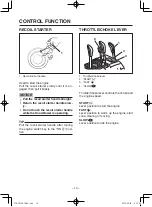
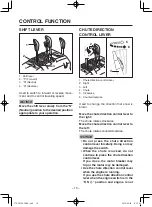
Page 19: ...l starter handle while the Snowblower is operating TIP Pull the recoil starter handle after turning the engine switch key to the ON 7 posi tion THROTTLE CHOKE LEVER 1 2 3 4 1 Throttle Choke lever 2 START 1 3 FAST 4 SLOW Throttle Choke lever controls the choke and the engine speed START 1 Lever position to start the engine FAST Lever position to warm up the engine start snow clearing or moving SLOW...

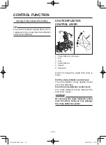
Page 20: ...now is blown Move the chute direction control lever to the right The chute rotates clockwise Move the chute direction control lever to the left The chute rotates counterclockwise NOTICE 9 Do not press the chute direction control lever forcefully Doing so may damage the switch 9 When the chute is locked do not continue to press the chute direction control lever If you do so the motor breaker may tr...

Page 21: ... Pull 3 Push 4 Chute deflector 5 Upward 6 Downward Used to change the angle that snow is blown Pull the chute deflector control lever The chute deflector moves upward to blow snow long distances Push the chute deflector control lever The chute deflector moves downward to blow snow nearby NOTICE Do not press the chute deflector control lever forcefully Doing so may damage the chute deflector system...

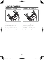
Page 22: ...ve clutch lever The Snowblower travels Release the drive clutch lever The Snowblower stops traveling AUGER CLUTCH LEVER 1 1 Auger clutch lever Used to rotate the auger Hold the auger clutch lever The auger rotates Release the auger clutch lever The auger stops rotating 7T0 28199 70 E0 indd 17 2019 05 01 9 22 55 ...

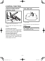
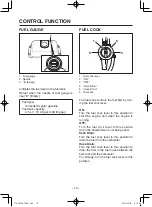
Page 23: ...lease the auger housing height control lever at the desired auger height To lower the auger housing Pull and hold the auger housing height control lever and return the handlebar to its original position Then release the auger housing height control lever FUEL TANK CAP 1 1 Fuel tank cap Turn the fuel tank cap counterclockwise to remove WARNING After refueling make sure the fuel tank cap is tightene...

Page 24: ...el flow by turn ing the fuel cock lever ON Turn the fuel cock lever to this position to start the engine and when the engine is running OFF Turn the fuel cock lever to this position when the Snowblower is not being used Carb Drain Turn the fuel cock lever to this position to drain the fuel from the carburetor Hose Drain Turn the fuel cock lever to this position to drain the fuel in the fuel hose b...

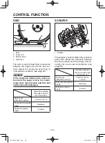
Page 25: ...en the auger end and the road surface Factory set Standard position 5 mm 0 197 in Concrete and asphalt roads Decrease Pebble and gravel roads Increase SCRAPER 1 1 Scraper The scraper is used to flatten the surface to plow snow Adjust the clearance between the road surface and the scraper end ac cording to road surface conditions see page 54 Clearance between the road surface and the scraper end Fa...

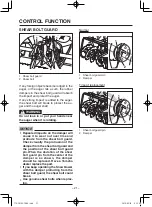
Page 26: ...se it to wear out over time and protrude from the shear bolt guard Check visually the protrusion of the damper from the shear bolt guard and the position of the shear bolt guard pin When the deviation of the shear bolt guard pin from the center of the damper is as shown the damper should be replaced Have a Yamaha dealer replace the part 9 If you keep operating the Snowblower with the damper protru...

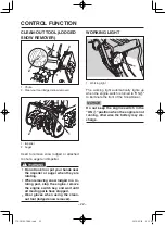
Page 27: ...ow lodged in a ro tating part stop the engine remove the engine switch key and wait until all moving parts have stopped 9 Wear gloves when using the clean out tool lodged snow remover WORKING LIGHT 1 1 Working light The working light automatically lights up when the engine switch is turned to ON 7 to illuminate the front of the Snowblower NOTICE Do not keep the engine switch in the ON 7 position w...

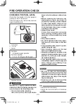
Page 28: ...y 9 The engine and muffler will still be very hot immediately after the en gine is stopped Conduct checks or maintenance after the engine and muffler have completely cooled down 9 If any abnormalities are discovered carry out maintenance by yourself or have a Yamaha dealer perform it for you CHECK BEFORE USE For safe and comfortable use of your Snowblower always check the following items before us...

Page 29: ...es 9 Always refuel alone If more than one person are nearby when refueling is taking place static electricity on their bodies may cause a spark 9 Only refuel outdoors 9 Do not fill gasoline above the speci fied level up to the base of the filler neck 9 If any gasoline spills wipe it up com pletely using dry rags 9 After refueling make sure the fuel tank cap is tightened securely 9 Should you happe...

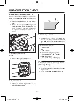
Page 30: ...ller cap 1 1 Engine oil filler cap 4 Make sure that the engine oil is at the correct engine oil level 1 1 Correct engine oil level 5 If the engine oil is below the correct en gine oil level fill up to the brim of the oil filler hole with the recommended engine oil Recommended brand YAMALUBE Type SAE 5W 30 Recommended engine oil grade API Service SE type or higher Engine oil quantity 0 6 L 0 63 US ...

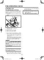
Page 31: ... is between the 10 C 0 C When the ambient temperature is below 20 C the oil might contract and oil level become below LOWER level NOTICE Do not check the transmission HST oil level immediately after the engine has stopped The oil might expand and cannot check the correct level TIP Position the Snowblower on a level surface when checking the oil level 3 If the transmission HST oil level is below th...

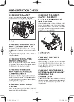
Page 32: ...the engine CHECKING THE EXHAUST SYSTEM After starting the engine check the exhaust system for any abnormalities CHECKING THE AUGER CLUTCH AND DRIVE CLUTCH FOR OPERATION MALFUNCTION After starting the engine operate both auger clutch lever and drive clutch lever Release each lever and make sure that the auger stops rotating and that the Snow blower stops see page 34 1 2 1 Auger clutch lever 2 Drive...

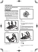
Page 33: ...nd drive clutch lever are releasing 1 2 1 Shift lever 2 N Neutral 2 1 1 Auger clutch lever 2 Drive clutch lever 2 Turn the fuel cock lever from the OFF position to the ON position 1 2 3 1 ON 2 OFF 3 Fuel cock lever 3 Move the throttle choke lever from the SLOW position to the START 1 position TIP If the engine is already warmed up it is not necessary to move the throttle choke lever to the START 1...

Page 34: ...ttle choke lever to the FAST position and then pull the recoil starter handle 6 After starting the engine leave the en gine to warm up for a while and then move the throttle choke lever from the START 1 position to the FAST position 1 3 2 1 Throttle Choke lever 2 START 1 3 FAST 7 When the engine is warmed up move the throttle choke lever from the FAST position to the SLOW position 1 2 3 1 Throttle...

Page 35: ...releasing 1 2 1 Shift lever 2 N Neutral 2 1 1 Auger clutch lever 2 Drive clutch lever 2 Turn the fuel cock lever from the OFF position to the ON position 1 2 3 1 ON 2 OFF 3 Fuel cock lever 3 Move the throttle choke lever from the SLOW position to the START 1 position TIP If the engine is already warmed up it is not necessary to move the throttle choke lever to the START 1 position 1 2 3 1 Throttle...

Page 36: ...n try again to start the engine STOP ON START 1 2 3 1 STOP 5 2 ON 7 3 START 6 5 After starting the engine leave the en gine to warm up for a while and then move the throttle choke lever from the START 1 position to the FAST position 1 3 2 1 Throttle Choke lever 2 START 1 3 FAST 6 When the engine is warmed up move the throttle choke lever from the FAST position to the SLOW position 1 2 3 1 Throttle...

Page 37: ... 1 ON 2 OFF 3 Fuel cock lever MOVING THE SNOWBLOWER 1 Use the auger housing height control lever to raise the auger to the highest position 1 2 1 Auger housing height control lever 2 Auger housing 2 Make sure that the shift lever is in the N Neutral position and move the throttle choke lever to the FAST po sition 1 2 1 Shift lever 2 N Neutral 7T0 28199 70 E0 indd 32 2019 05 01 9 22 58 ...

Page 38: ...ion and then hold the drive clutch lever 9 Operate the drive clutch lever slowly 1 1 Drive clutch lever 4 Move the shift lever from the N Neu tral position to the F Forward or R Reverse position NOTICE Operate the shift lever slowly 1 2 3 4 1 Shift lever 2 F Forward 3 N Neutral 4 R Reverse 7T0 28199 70 E0 indd 33 2019 05 01 9 22 58 ...

Page 39: ...on to blow the snow by using the chute direction control lever 1 2 3 4 5 1 Chute direction control lever 2 Right 3 Left 4 Clockwise 5 Counterclockwise 3 Adjust the snow blowing distance by us ing the chute deflector control lever 1 2 3 4 5 1 Chute deflector control lever 2 Pull 3 Push 4 Upward 5 Downward 4 Hold the auger clutch lever The auger starts rotating WARNING After first ensuring the snow ...

Page 40: ...ontrolled with your right hand 6 Move the shift lever from the N Neu tral position to the F Forward or R Reverse position NOTICE Operate the shift lever slowly TIP 9 If the engine speed drops excessively and snow is not being blown properly you may be driving the machine too quickly Reduce speed 9 Snow is blown more effectively when the Snowblower is driven slowly 1 2 3 4 1 Shift lever 2 F Forward...

Page 41: ... 36 OPERATION 1 2 1 Auger clutch lever 2 Drive clutch lever 7T0 28199 70 E0 indd 36 2019 05 01 9 22 59 ...

Page 42: ...moving Rotates Stops Locked Useful information for operation CLEAR SNOW WHILE TRAVELING Traveling speed auger movement and other operations are controlled with your right hand EMERGENCY STOP or OPERATION STOP CLEANS OUT THE AUGER Discharges snow from the auger If the auger clutch lever is held once while you are holding the drive clutch lever the auger clutch lever will become fixed The Snowblower...

Page 43: ...ter clearing snow hold the auger clutch lever to clear the snow on the auger and impeller Leaving snow on the auger and impeller could cause freeze and damage 1 1 Auger clutch lever 4 Release the auger clutch lever 1 1 Auger clutch lever 5 Move the throttle choke lever to the SLOW position Turn the engine switch key to the STOP 5 position to stop the engine and then turn the fuel cock lever to the...

Page 44: ...tart the engine 9 Position the Snowblower on a level surface before beginning the follow ing procedure 1 Remove the sprocket pin from the sprocket wheel by pulling on the ring 2 Insert the sprocket pin into the hole of the wheel axle and then fold the ring of the sprocket pin TIP Remove the sprocket pin from the both side of the wheels 1 2 3 4 1 Ring 2 Sprocket pin 3 Hole 4 Sprocket wheel 3 The sp...

Page 45: ... above 4000 ft 1219 me ters If you operate your engine at altitudes above 4000 ft 1219 meters consistently have your local Yamaha dealer perform the necessary carburetor modification This engine should be operated in its original configuration below 4000 ft 1219 meters as damage may occur if high altitude car buretor kit is installed and operated below 4000 ft 1219 meters 7T0 28199 70 E0 indd 40 2...

Page 46: ...u CHECK BEFORE USE The customer needs to perform the routine inspection see page 23 If any problems are dis covered during the inspection contact a Yamaha dealer and request an inspection or main tenance PERIODIC INSPECTION Yamaha dealers perform periodic inspections when requested by the customer The customer is responsible for contacting their Yamaha dealer to request a periodic inspec tion Init...

Page 47: ... 3 3 Skid 9 Mounting and parallel layout 3 3 3 Auger height control 9 Working conditions 3 3 3 Engine switch 9 Working conditions 3 3 3 Auger brake 9 Working conditions 3 3 3 Controls 9 Throttle Choke lever operation 3 3 3 9 Auger clutch operation and working conditions 3 3 3 9 Shift lever operation 3 3 3 9 Shift lever adjustment status 3 3 3 9 Drive clutch operation and working conditions 3 3 3 3...

Page 48: ...conditions 3 3 3 3 9 Compression pressure 3 9 Valve clearance 3 9 Removal of carbon from cylinder head After every 125 Hrs Lubrication system 9 Oil leakage 3 9 Engine oil level 3 9 Engine oil change 3 3 Fuel system 9 Fuel leakage 3 3 9 Carburetor throttle valve and choke valve condi tions 3 3 9 Carburetor adjustment conditions 3 3 9 Fuel level 3 9 Fuel hose replacement Every 4 years Muffler 9 Chec...

Page 49: ... times After that change the engine oil each time the winter season begins 1 Start the engine and warm up for 2 3 minutes 2 Stop the engine and remove the engine switch key 3 Remove the screws 1 Then remove the screws 2 and collars and the right side cover 1 3 4 2 1 Screw 1 2 Screw 2 3 Collar 4 Right side cover 4 Remove the engine oil filler cap 1 1 Engine oil filler cap 5 Remove the screws 1 Then...

Page 50: ... Oil filler hole 1 1 Correct engine oil level Engine oil quantity 0 6 L 0 63 US qt 0 53 Imp qt Recommended engine oil See page 25 TIP If any engine oil spills wipe it up completely using dry rags 10 Install and tighten the engine oil filler cap securely 11 Install the right side cover and collars to their original positions and tighten the screws 2 Then tighten the screws 1 12 Install the left sid...

Page 51: ... level mark of the transmission HST oil res ervoir 1 2 3 1 Transmission HST oil reservoir 2 Maximum level mark UPPER 3 Minimum level mark LOWER NOTICE 9 Make sure that no foreign material such as dirt enters the oil reservoir during refilling 9 Use the recommended transmission HST oil only Recommended transmission HST oil Diesel engine oil SAE 10W 30 Class CD or higher 4 Install the diaphragm so t...

Page 52: ...IL If necessary have a Yamaha dealer change the worm case oil TIP For the first worm case oil change change the worm case oil after 20 operating hours that is when you have refueled four times After that change the worm case oil each time the winter season begins 7T0 28199 70 E0 indd 47 2019 05 01 9 23 01 ...

Page 53: ...on could cause high voltage leaks resulting in a fire and serious burns 1 Stop the engine and remove the engine switch key 2 Remove the spark plug cap 1 2 1 Spark plug cap 2 Spark plug 3 Remove the spark plug using a spark plug wrench 1 2 1 Spark plug cap 2 Spark plug wrench 4 Check the spark plug for any signs of burns Burn marks on spark plugs are usually medium to light tan If there are any bla...

Page 54: ...STRAINER WARNING Gasoline is a highly volatile and flam mable fuel When handling gasoline be sure to observe the following points 9 Do not smoke while carrying out a service Also never put any other open flames close to the Snowblower while servic ing 9 Before starting the service discharge any static electricity on yourself by touching a metal chassis or other metal object 1 Stop the engine and r...

Page 55: ... the ON po sition and make sure that no fuel leaks out ADJUSTING THE SKIDS WARNING Position the Snowblower on a level sur face Adjust the clearance between the auger end and the road surface correctly accord ing to the road conditions 1 Stop the engine and remove the engine switch key 2 Check the clearance between the auger end and the road surface 1 2 3 4 1 Skid 2 Auger end 3 Road surface 4 Clear...

Page 56: ...using the auger housing height control lever 7 Check the clearance between the auger end and the road surface NOTICE If the clearance between the road sur face and the auger end is too small auger wear may increase and the road surface could be damaged TIP Adjust the left and right skids so they are both the same height 8 Tighten the nuts of skid to the specified torque Tightening torque Nut 16 N ...

Page 57: ...w remover 1 Stop the engine and remove the engine switch key 2 Be sure to use the clean out tool lodged snow remover to remove snow and other obstacles from the auger housing 3 Remove the locknuts the shear bolts and the washers 1 1 2 3 3 3 3 1 Locknut 2 Shear bolt 3 Washer 4 Install the new shear bolts with their washers 5 Install the new locknuts and then tighten them to the specified torque Tig...

Page 58: ...dged snow remover 1 Stop the engine and remove the engine switch key 2 Be sure to use the clean out tool lodged snow remover to remove snow and other obstacles from the auger housing 3 Remove the locknut collar and the shear bolt 1 3 4 2 1 Shear bolt 2 Impeller 3 Collar 4 Locknut 4 Install the new shear bolt with the col lar and then install and tighten the new locknut to the specified torque Tigh...

Page 59: ... Decrease TIP Adjust the clearance between the scraper end and the road surface so that it be comes equal to or greater than the clear ance between the auger end and the road surface 1 2 1 Clearance between scraper end and road surface 2 Clearance between auger end and road sur face 5 Be sure the scraper is horizontal and then tighten the nuts and bolts to the specified torques Tightening torque N...

Page 60: ...approximately 5 kgf 11 lbf force Slack 11 16 mm 0 43 0 63 in when pressed by 5 kgf 11 lbf force 1 1 Slack TIP Check the track for wear and damage at the same time Adjusting 1 Stop the engine and remove the engine switch key 2 Loosen the wheel nut on both sides 1 1 Wheel nut 3 Loosen the locknut and adjust the track slack by turning the adjusting bolt A B 1 2 1 Locknut 2 Adjusting bolt Slack Direct...

Page 61: ...ower is stuck in a rut the sprocket pin will be cut to protect the driving system If the sprocket pin is broken replace it im mediately WARNING Position the Snowblower on a level sur face 1 Stop the engine and remove the engine switch key 2 If the broken sprocket pin remains in sprocket wheel or wheel axle remove it 1 2 1 Sprocket wheel 2 Wheel axle 3 Install a new sprocket pin 7T0 28199 70 E0 ind...

Page 62: ...e burns Avoid any contact with skin eyes or cloth ing and always shield your eyes when working near batteries In case of contact administer the following FIRST AID 9 EXTERNAL Flush with plenty of wa ter 9 INTERNAL Drink large quantities of water or milk and immediately call a physician 9 EYES Flush with water for 15 min utes and seek prompt medical atten tion 0Batteries produce explosive hydro gen...

Page 63: ...ht side cover 3 Remove the battery band 4 First disconnect the battery negative lead from the negative battery terminal and then disconnect the battery positive lead from the positive battery terminal 1 2 3 1 Battery band 2 Negative lead 3 Positive lead 5 Remove the battery Installing the battery Install the battery by performing the remov al procedures in the reverse order Cleaning the terminals ...

Page 64: ...keep the battery charged Stor ing a discharged battery can cause per manent battery damage REPLACING THE FUSE WARNING 9 Always use a fuse of the specified rating and never use a substitute object in place of the proper fuse An improper fuse or a substitute object can cause damage to the electrical system which could lead to a fire 9 Avoid spraying water around the fuse when washing the Snowblower ...

Page 65: ...IP If the fuse immediately blows again have a Yamaha dealer check the electrical system 4 Install the right side cover and collars to their original positions and tighten the screws 2 Then tighten the screws 1 PERIODIC MAINTENANCE 7T0 28199 70 E0 indd 60 2019 05 01 9 23 03 ...

Page 66: ... moving parts 9 Inner end of each cable 9 Moving parts of auger clutch lever and clutch lever shaft 9 Moving parts of ratchet cam 9 Inner and outer periphery of ratchet cam mounting collar 9 Throttle Choke lever moving parts 1 2 3 4 5 6 1 Moving parts of chute deflector control lever 2 Shift lever moving parts 3 Drive clutch lever moving parts 4 Moving parts of auger clutch lever and clutch lever ...

Page 67: ... 62 PERIODIC MAINTENANCE 7 7 8 7 Chute assembly moving parts 8 Chute motor gears and ring gears 7T0 28199 70 E0 indd 62 2019 05 01 9 23 03 ...

Page 68: ...hale gasoline vapor or get gasoline in your eyes seek immediate medical attention 9 If gasoline spills onto your skin im mediately wash it off with soap and water Change your clothing if any gasoline spills on them NOTICE 9 Extract the fuel from the fuel tank If any fuel remains in the fuel tank it may deteriorate and result in dif ficulty starting the engine in the next season 9 If gasoline spill...

Page 69: ...e OFF position 1 2 3 1 ON 2 OFF 3 Fuel cock lever 6 Place a suitable container below the fuel cock to collect the drained gasoline Remove the ring nut of the fuel cock and then remove the fuel strainer cup 1 2 1 Ring nut 2 Fuel strainer cup 1 1 Container TIP If the ring nut is too tight loosen it using a pliers or other tool 7 Turn the fuel cock lever from the OFF position to the ON position and d...

Page 70: ...ain 3 Fuel cock lever 4 Fuel drain hose NOTICE Immediately wipe off spilled fuel with a clean dry soft cloth since fuel may deteriorate painted surfaces or plastic parts 10 After all remaining gasoline has been extracted from the fuel tank spray a rust inhibitor against the fuel tank walls 11 Tighten the fuel tank cap securely 12 Install the fuel strainer cup and the ring nut then tighten the ring...

Page 71: ...ty and well ventilated space indoors NOTICE To attach a cover or similar device to the Snowblower wait until the engine and muffler have completely cooled down LONG TERM If the Snowblower is not used for a long pe riod of time follow the steps below to keep it in good condition 1 Follow steps 1 16 under SHORT TERM 2 Clean each part of the Snowblower and implement rust treatment 3 Place a cover on ...

Page 72: ...US gal 0 99 Imp gal Lubrication system Wet sump forced spray type Recommended en gine oil YAMALUBE SAE 5W 30 API Service SE type or higher Engine oil quantity 0 6 L 0 63 US qt 0 53 Imp qt Recommended transmission HST oil Diesel engine oil SAE 10W 30 Class CD or higher Transmission HST oil quantity 0 92 L 0 97 US qt 0 81 Imp qt Starting method Recoil or Electric starter Spark plug NGK BPR4ES Spark ...

Page 73: ... in the SPECIFICATIONS is the net power output tested on an engine model and measured at 3600 r min Actual power output for the engine installed in the Snowblower will vary depending on numerous fac tors including the operating speed of the engine environmental conditions and other variables 7T0 28199 70 E0 indd 68 2019 05 01 9 23 04 ...

Page 74: ...ING THE FUEL LEVEL 24 CHECKING THE HANDLEBAR FOR LOOSENESS OR PLAY 27 CHECKING THE STARTER MOTOR OPERATION 27 CHECKING THE TRANSMISSION HST OIL 26 CHUTE DEFLECTOR CONTROL LEVER 16 CHUTE DIRECTION CONTROL LEVER 15 CLEANING THE FUEL STRAINER 49 CLEAN OUT TOOL LODGED SNOW REMOVER 22 CLEARING SNOW 34 CONTROL FUNCTION 13 D DESCRIPTION 9 DRIVE CLUTCH LEVER 17 E ENGINE SWITCH 13 F FUEL COCK 19 FUEL GAUGE...

Page 75: ... SAFETY INFORMATION 2 SCRAPER 20 SHEAR BOLT GUARD 21 SHIFT LEVER 15 SKID 20 SPECIFICATIONS 67 STARTING THE ENGINE FOR ELECTRIC START 30 STARTING THE ENGINE FOR RECOIL START 28 STOPPING THE ENGINE 32 STOPPING THE SNOWBLOWER 38 STORAGE 63 T THROTTLE CHOKE LEVER 14 W WORKING LIGHT 22 INDEX 7T0 28199 70 E0 indd 70 2019 05 01 9 23 04 ...

Page 76: ...YAMAHA MOTOR CO LTD PRINTED IN JAPAN 2019 05 1 E 7T0 28199 70 E0 7T0 28199 70 E0 indd 71 2019 05 01 9 23 04 ...

Reviews: