ELECTRICAL COMPONENTS
8-60
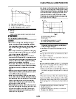
d. Adjust the voltage so that the current is at
the standard charging level.
e. Set the time according to the charging time
suitable for the open-circuit voltage.
f. If charging requires more than 5 hours, it is
advisable to check the charging current after
a lapse of 5 hours. If there is any change in
the amperage, readjust the voltage to obtain
the standard charging current.
g. Measure the battery open-circuit voltage af-
ter leaving the battery unused for more than
30 minutes.
▲▲▲▲▲▲▲▲▲▲▲▲▲▲▲▲▲▲▲▲▲▲▲▲▲▲▲▲▲▲▲▲
▼▼▼▼▼▼▼▼▼▼▼▼▼▼▼▼▼▼▼▼▼▼▼▼▼▼▼▼▼▼▼▼
Charging method using a constant volt-
age charger
a. Measure the open-circuit voltage prior to
charging.
TIP
Voltage should be measured 30 minutes after
the engine is stopped.
b. Connect a charger and ammeter to the bat-
tery and start charging.
c. Make sure that the current is higher than the
standard charging current written on the bat-
tery.
TIP
If the current is lower than the standard charg-
ing current written on the battery, this type of
battery charger cannot charge the VRLA (Valve
Regulated Lead Acid) battery. A variable volt-
age charger is recommended.
d. Charge the battery until the battery’s charg-
ing voltage is 15 V.
TIP
Set the charging time at 20 hours (maximum).
e. Measure the battery open-circuit voltage af-
ter leaving the battery unused for more than
30 minutes.
▲▲▲▲▲▲▲▲▲▲▲▲▲▲▲▲▲▲▲▲▲▲▲▲▲▲▲▲▲▲▲▲
6. Install:
• Battery terminals
7. Connect:
• Battery leads
(to the battery terminals)
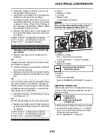
ECA
NOTICE
First, connect the positive battery lead “1”,
and then the negative battery lead “2”.
8. Check:
• Battery terminals
Dirt
Clean with a wire brush.
Loose connection
Connect properly.
9. Lubricate:
• Battery terminals
10.Install:
• Seat
• Side cover (left/right)
Refer to “GENERAL CHASSIS” on page 4-
1.
EASB296351
CHECKING THE RELAYS
Check each switch for continuity with the pock-
et tester. If the continuity reading is incorrect,
replace the relay.
1. Disconnect the relay from the wire harness.
2. Connect the pocket tester (
1) and bat-
tery (12 V) to the relay terminal as shown.
Check the relay operation.
Out of specification
Replace.
12.8 V or more --- Charging is complete.
12.7 V or less --- Recharging is required.
Under 12.0 V --- Replace the battery.
12.8 V or more --- Charging is complete.
12.7 V or less --- Recharging is required.
Under 12.0 V --- Replace the battery.
Recommended lubricant
Dielectric grease
Pocket tester
90890-03112
Analog pocket tester
YU-03112-C
2
1
Summary of Contents for YZ 2016 Series
Page 6: ...EASB296006 YAMAHA MOTOR CORPORATION U S A YZ MOTORCYCLE LIMITED WARRANTY...
Page 10: ......
Page 31: ...CONTROL FUNCTIONS 1 19 a 2...
Page 63: ...LUBRICATION POINTS AND LUBRICANT TYPES 2 22...
Page 66: ...LUBRICATION SYSTEM CHART AND DIAGRAMS 2 25...
Page 68: ...LUBRICATION SYSTEM CHART AND DIAGRAMS 2 27...
Page 70: ...LUBRICATION SYSTEM CHART AND DIAGRAMS 2 29...
Page 72: ...CABLE ROUTING DIAGRAM 2 31 EASB296066 CABLE ROUTING DIAGRAM...
Page 74: ...CABLE ROUTING DIAGRAM 2 33...
Page 76: ...CABLE ROUTING DIAGRAM 2 35...
Page 78: ...CABLE ROUTING DIAGRAM 2 37...
Page 80: ...CABLE ROUTING DIAGRAM 2 39...
Page 82: ...CABLE ROUTING DIAGRAM 2 41...
Page 84: ...CABLE ROUTING DIAGRAM 2 43...
Page 86: ...CABLE ROUTING DIAGRAM 2 45...
Page 262: ...OIL PUMP AND BALANCER GEAR 5 63 a 2 10 b 2 9 1 b 5 3 a 4 10 5 9 3 E c d 6 7 8 8 b 6...
Page 282: ...TRANSMISSION 5 83...
Page 302: ...8 CHECKING THE INTAKE AIR TEMPERATURE SENSOR 8 68 CHECKING THE FUEL INJECTOR 8 68...
Page 317: ...CHARGING SYSTEM 8 15...
Page 321: ...COOLING SYSTEM For JPN 8 19...
Page 351: ...FUEL PUMP SYSTEM 8 49...
Page 352: ...ELECTRICAL COMPONENTS 8 50 EASB296346 ELECTRICAL COMPONENTS EASB296347 7 8 9 1 3 2 4 5 6...
Page 354: ...ELECTRICAL COMPONENTS 8 52 11 10 9 2 3 1 6 7 8 4 5...
Page 356: ...ELECTRICAL COMPONENTS 8 54 EASB296348 CHECKING THE SWITCHES 4 1 3 2 B B Sb B B B B B B B B...
Page 378: ...LIST OF SELF DIAGNOSTIC AND FAIL SAFE ACTIONS 9 7...


