FRONT FORK
4-44
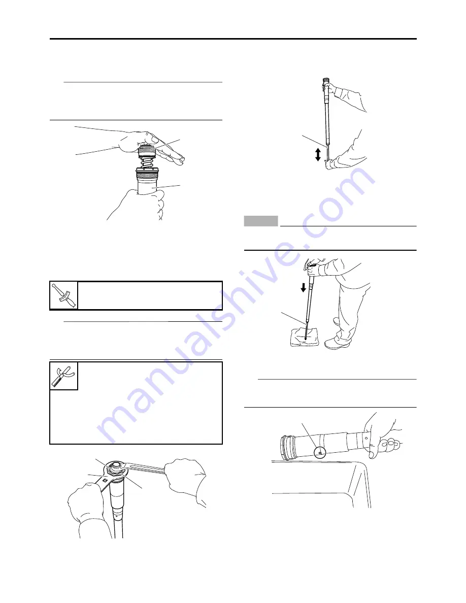
7. Install:
• Base valve “1”
(to the damper assembly “2”)
TIP
First bring the damper rod pressure to a maxi-
mum. Then install the base valve while releas-
ing the damper rod pressure.
8. Check:
• Damper assembly
Not fully stretched
Repeat the steps 1 to
7.
9. Tighten:
• Base valve “1”
TIP
Hold the damper assembly with the cap bolt
ring wrench “2” and use the cap bolt wrench “3”
to tighten the base valve.
10.After filling, pump the damper assembly “1”
slowly up and down more than 10 times to
distribute the fork oil.
11.While protecting the damper assembly “1”
with a cloth and compressing fully, allow ex-
cessive oil to overflow on the base valve
side.
ECA
NOTICE
Take care not to damage the damper assem-
bly.
12.Allow the overflowing oil to escape at the
hole “a” in the damper assembly.
TIP
The overflow measures about 10 cm
3
(0.34 US
oz, 0.35 lmp.oz).
13.Check:
• Damper assembly smooth movement
Tightness/binding/rough spots
Repeat
the steps 1 to 12.
Base valve
28 N·m (2.8 kgf·m, 21 lb·ft)
Cap bolt wrench
90890-01500
Cap bolt wrench
YM-01500
Cap bolt ring wrench
90890-01501
Cap bolt ring wrench
YM-01501
1
2
T
R
.
.
1
2
3
1
1
a
Summary of Contents for YZ 2018 Series
Page 6: ...EASB916006 YAMAHA MOTOR CORPORATION U S A YZ MOTORCYCLE LIMITED WARRANTY...
Page 10: ......
Page 40: ...MOTORCYCLE CARE AND STORAGE 1 28...
Page 64: ...LUBRICATION SYSTEM CHART AND DIAGRAMS 2 23...
Page 66: ...LUBRICATION SYSTEM CHART AND DIAGRAMS 2 25...
Page 68: ...LUBRICATION SYSTEM CHART AND DIAGRAMS 2 27...
Page 70: ...CABLE ROUTING DIAGRAM 2 29 EASB29B065 CABLE ROUTING DIAGRAM...
Page 72: ...CABLE ROUTING DIAGRAM 2 31...
Page 74: ...CABLE ROUTING DIAGRAM 2 33...
Page 76: ...CABLE ROUTING DIAGRAM 2 35...
Page 78: ...CABLE ROUTING DIAGRAM 2 37...
Page 80: ...CABLE ROUTING DIAGRAM 2 39...
Page 82: ...CABLE ROUTING DIAGRAM 2 41...
Page 84: ...CABLE ROUTING DIAGRAM 2 43...
Page 255: ...OIL PUMP AND BALANCER GEAR 5 58 a 2 10 b 2 9 1 b 5 3 a 4 10 5 9 3 E c d 6 7 8 8 b 6...
Page 276: ...TRANSMISSION 5 79...
Page 290: ...FUEL TANK 7 5 A Left B Right 1 1 A 0 mm 0 in B 1 1 15 mm 0 59 in...
Page 296: ...THROTTLE BODY 7 11...
Page 299: ......
Page 313: ...CHARGING SYSTEM 8 14...
Page 321: ...COOLING SYSTEM For JPN 8 22...
Page 351: ...FUEL PUMP SYSTEM 8 52 EASB29B345...
Page 352: ...ELECTRICAL COMPONENTS 8 53 ELECTRICAL COMPONENTS EASB29B346 9 10 11 1 3 2 4 5 6 7 8...
Page 354: ...ELECTRICAL COMPONENTS 8 55 11 10 9 2 3 1 6 7 8 4 5...
Page 356: ...ELECTRICAL COMPONENTS 8 57 EASB29B347 CHECKING THE SWITCHES 4 1 3 2 B B Sb B B B B B B B B...
Page 372: ...ELECTRICAL COMPONENTS 8 73 c Measure the fuel injector resistance...


