STEERING HEAD
4-52
EASB29B177
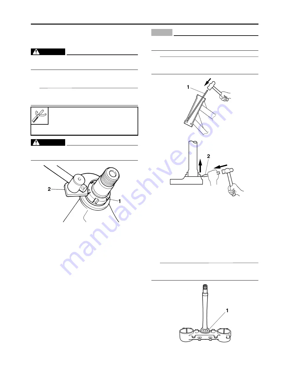
REMOVING THE LOWER BRACKET
1. Use a suitable stand to raise the front wheel
off the ground.
EWA
WARNING
Securely support the vehicle so that there is
no danger of it falling over.
2. Remove:
• Ring nut “1”
TIP
Remove the ring nut with the steering nut
wrench “2”.
EWA
WARNING
Securely support the lower bracket so that
there is no danger of it falling.
EASB29B178
CHECKING THE STEERING HEAD
1. Wash with kerosene:
• Bearing
• Bearing races
2. Check:
• Bearing
• Bearing races
Damage/pitting
Replace.
3. Replace:
• Bearing
• Bearing races
▼▼▼▼▼▼▼▼▼▼▼▼▼▼▼▼▼▼▼▼▼▼▼▼▼▼▼▼▼▼▼▼
a. Remove the bearing race from the steering
head pipe with a long rod “1” and a hammer.
b. Remove the bearing race from the lower
bracket with a chisel “2” and a hammer.
c. Install a new bearing race.
ECA
NOTICE
If the bearing race is not installed properly,
the steering head pipe could be damaged.
TIP
Always replace the bearing and the bearing
race as a set.
▲▲▲▲▲▲▲▲▲▲▲▲▲▲▲▲▲▲▲▲▲▲▲▲▲▲▲▲▲▲▲▲
4. Check:
• Upper bracket
• Lower bracket
(along with the steering stem)
Bends/cracks/damage
Replace.
EASB29B179
INSTALLING THE STEERING HEAD
1. Install:
• Lower bearing “1”
TIP
Apply the lithium-soap-based grease on the
dust seal lip and bearing inner circumference.
Steering nut wrench
90890-01403
Exhaust flange nut wrench
YU-A9472
Summary of Contents for YZ 2018 Series
Page 6: ...EASB916006 YAMAHA MOTOR CORPORATION U S A YZ MOTORCYCLE LIMITED WARRANTY...
Page 10: ......
Page 40: ...MOTORCYCLE CARE AND STORAGE 1 28...
Page 64: ...LUBRICATION SYSTEM CHART AND DIAGRAMS 2 23...
Page 66: ...LUBRICATION SYSTEM CHART AND DIAGRAMS 2 25...
Page 68: ...LUBRICATION SYSTEM CHART AND DIAGRAMS 2 27...
Page 70: ...CABLE ROUTING DIAGRAM 2 29 EASB29B065 CABLE ROUTING DIAGRAM...
Page 72: ...CABLE ROUTING DIAGRAM 2 31...
Page 74: ...CABLE ROUTING DIAGRAM 2 33...
Page 76: ...CABLE ROUTING DIAGRAM 2 35...
Page 78: ...CABLE ROUTING DIAGRAM 2 37...
Page 80: ...CABLE ROUTING DIAGRAM 2 39...
Page 82: ...CABLE ROUTING DIAGRAM 2 41...
Page 84: ...CABLE ROUTING DIAGRAM 2 43...
Page 255: ...OIL PUMP AND BALANCER GEAR 5 58 a 2 10 b 2 9 1 b 5 3 a 4 10 5 9 3 E c d 6 7 8 8 b 6...
Page 276: ...TRANSMISSION 5 79...
Page 290: ...FUEL TANK 7 5 A Left B Right 1 1 A 0 mm 0 in B 1 1 15 mm 0 59 in...
Page 296: ...THROTTLE BODY 7 11...
Page 299: ......
Page 313: ...CHARGING SYSTEM 8 14...
Page 321: ...COOLING SYSTEM For JPN 8 22...
Page 351: ...FUEL PUMP SYSTEM 8 52 EASB29B345...
Page 352: ...ELECTRICAL COMPONENTS 8 53 ELECTRICAL COMPONENTS EASB29B346 9 10 11 1 3 2 4 5 6 7 8...
Page 354: ...ELECTRICAL COMPONENTS 8 55 11 10 9 2 3 1 6 7 8 4 5...
Page 356: ...ELECTRICAL COMPONENTS 8 57 EASB29B347 CHECKING THE SWITCHES 4 1 3 2 B B Sb B B B B B B B B...
Page 372: ...ELECTRICAL COMPONENTS 8 73 c Measure the fuel injector resistance...


