FUEL INJECTION SYSTEM
8-25
EASB29B338
ECU SELF-DIAGNOSTIC FUNCTION
The ECU is equipped with a self-diagnostic function in order to ensure that the fuel injection system
is operating normally. If this function detects a malfunction in the system, it immediately operates the
engine under substitute characteristics and illuminates the engine trouble warning light to alert the
rider that a malfunction has occurred in the system. Once a malfunction has been detected, a fault
code number is stored in the memory of the ECU.
• To inform the rider that the fuel injection system is not functioning, the engine trouble warning light
flashes while the start switch is being pushed to start the engine.
• If a malfunction is detected in the system by the self-diagnostic function, the ECU provides an ap-
propriate substitute characteristic operation, and alerts the rider of the detected malfunction by illu-
minating the engine trouble warning light.
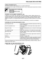
Engine trouble warning light indication and fuel injection system operation
* The engine trouble warning light flashes when any one of the following conditions is present and
the start switch is pushed:
Checking the engine trouble warning light
The engine trouble warning light comes on for around 2 seconds when pushing the start switch to
turn on the engine trouble warning light comes on while the start switch is being pushed.
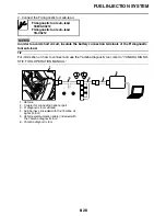
Warning light indica-
tion
ECU operation
Fuel injection opera-
tion
Vehicle operation
Flashing*
Warning provided
when unable to start
engine
Operation stopped
Cannot be operated
Remains on
Malfunction detected
Operated with substi-
tute characteristics in
accordance with the
description of the mal-
function
Can or cannot be oper-
ated depending on the
fault code
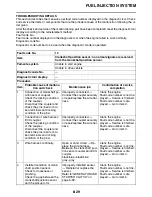
12:
Crankshaft position sensor
41:
Lean angle sensor
(open or short circuit)
30:
Lean angle sensor
(latch up detected)
50:
ECU internal malfunction
(faulty ECU memory)
33:
Ignition coil
(Malfunction detected in the primary wire
of the ignition coil)
a. Start switch is not being pushed.
b. Start swich is being pushed.
c. Engine trouble warning light goes off
d. Engine trouble warning light comes on for
around 2 seconds
a
b
c
d
c
Summary of Contents for YZ 2018 Series
Page 6: ...EASB916006 YAMAHA MOTOR CORPORATION U S A YZ MOTORCYCLE LIMITED WARRANTY...
Page 10: ......
Page 40: ...MOTORCYCLE CARE AND STORAGE 1 28...
Page 64: ...LUBRICATION SYSTEM CHART AND DIAGRAMS 2 23...
Page 66: ...LUBRICATION SYSTEM CHART AND DIAGRAMS 2 25...
Page 68: ...LUBRICATION SYSTEM CHART AND DIAGRAMS 2 27...
Page 70: ...CABLE ROUTING DIAGRAM 2 29 EASB29B065 CABLE ROUTING DIAGRAM...
Page 72: ...CABLE ROUTING DIAGRAM 2 31...
Page 74: ...CABLE ROUTING DIAGRAM 2 33...
Page 76: ...CABLE ROUTING DIAGRAM 2 35...
Page 78: ...CABLE ROUTING DIAGRAM 2 37...
Page 80: ...CABLE ROUTING DIAGRAM 2 39...
Page 82: ...CABLE ROUTING DIAGRAM 2 41...
Page 84: ...CABLE ROUTING DIAGRAM 2 43...
Page 255: ...OIL PUMP AND BALANCER GEAR 5 58 a 2 10 b 2 9 1 b 5 3 a 4 10 5 9 3 E c d 6 7 8 8 b 6...
Page 276: ...TRANSMISSION 5 79...
Page 290: ...FUEL TANK 7 5 A Left B Right 1 1 A 0 mm 0 in B 1 1 15 mm 0 59 in...
Page 296: ...THROTTLE BODY 7 11...
Page 299: ......
Page 313: ...CHARGING SYSTEM 8 14...
Page 321: ...COOLING SYSTEM For JPN 8 22...
Page 351: ...FUEL PUMP SYSTEM 8 52 EASB29B345...
Page 352: ...ELECTRICAL COMPONENTS 8 53 ELECTRICAL COMPONENTS EASB29B346 9 10 11 1 3 2 4 5 6 7 8...
Page 354: ...ELECTRICAL COMPONENTS 8 55 11 10 9 2 3 1 6 7 8 4 5...
Page 356: ...ELECTRICAL COMPONENTS 8 57 EASB29B347 CHECKING THE SWITCHES 4 1 3 2 B B Sb B B B B B B B B...
Page 372: ...ELECTRICAL COMPONENTS 8 73 c Measure the fuel injector resistance...


