KICK STARTER KIT (OPTIONAL PARTS)
10-14
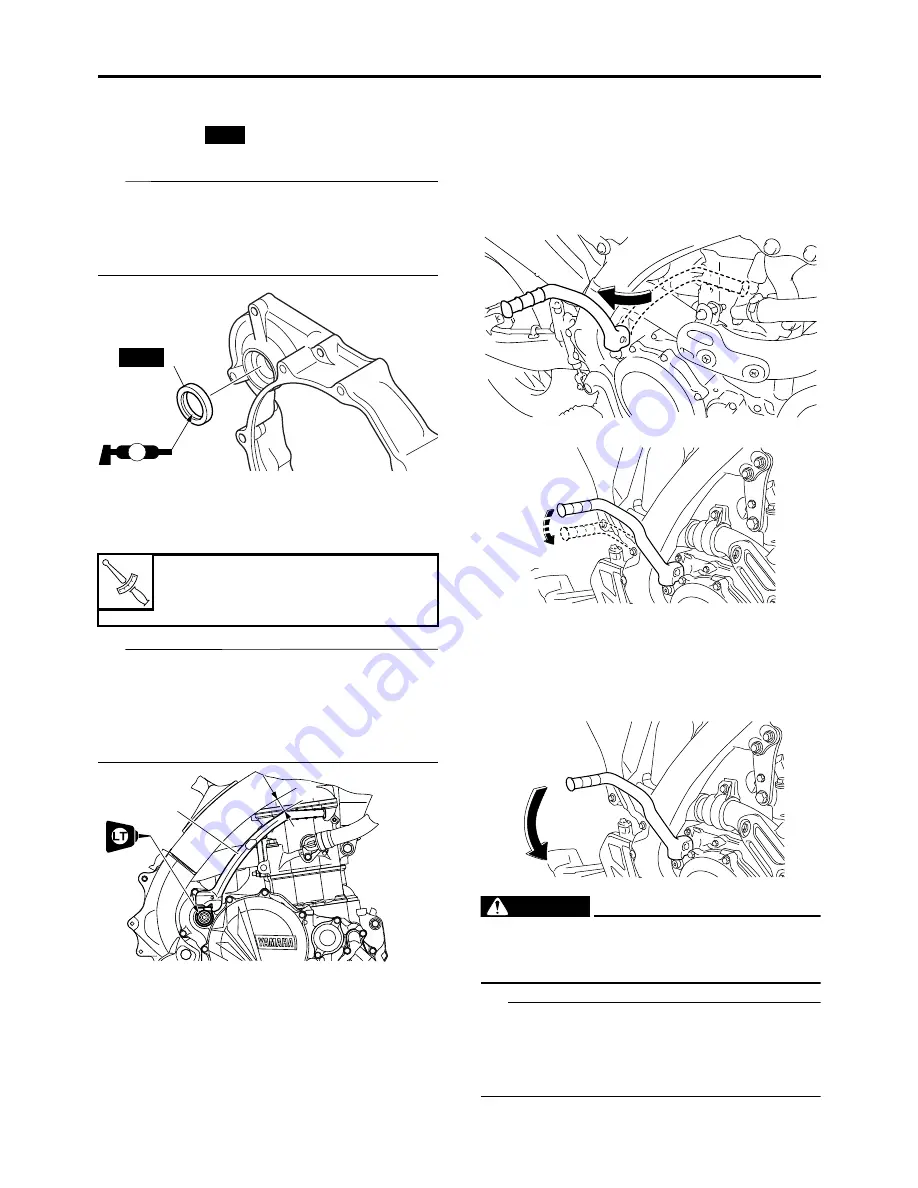
Installing the kickstarter lever
1. Install:
• Oil seal “1”
(to the right crank case cover)
TIP
• Apply the lithium-soap-based grease on the
oil seal lip.
• Install the oil seal with its numbers facing the
outside.
2. Install:
• Kickstarter lever “1”
• Washer
• Bolt (kickstarter lever)
TIP
Install so that there is a clearance “a” of 5 mm
(0.2 in) or more between the kickstarter lever
and the frame and that the kickstarter lever
does not contact the right crankcase cover
when it is pulled.
EASB29B404
STARTING THE ENGINE
Starting with the kickstarter
When using the kickstarter to start the engine,
follow the procedures as described below.
1. Fold out the kickstarter lever, push it down
lightly with your foot until resistance is felt.
2. With the throttle fully closed,push the kick-
starter down lightly until the gears engage,
and then push it down smoothly but forceful-
ly.
EWA
WARNING
Do not open the throttle while kicking the
kickstarter lever. Otherwise, the kickstarter
lever may kick back.
TIP
If the engine fails to start, push the engine stop
switch and give the kickstarter 10 to 20 slow
kicks at full throttle in order to clear the engine
of the rich air-fuel mixture retained in it.
Bolt (kickstarter lever)
33 N·m (3.3 kgf·m, 24 lb·ft)
LOCTITE®
New
1
New
LS
T
R
.
.
1
a
Summary of Contents for YZ 2018 Series
Page 6: ...EASB916006 YAMAHA MOTOR CORPORATION U S A YZ MOTORCYCLE LIMITED WARRANTY...
Page 10: ......
Page 40: ...MOTORCYCLE CARE AND STORAGE 1 28...
Page 64: ...LUBRICATION SYSTEM CHART AND DIAGRAMS 2 23...
Page 66: ...LUBRICATION SYSTEM CHART AND DIAGRAMS 2 25...
Page 68: ...LUBRICATION SYSTEM CHART AND DIAGRAMS 2 27...
Page 70: ...CABLE ROUTING DIAGRAM 2 29 EASB29B065 CABLE ROUTING DIAGRAM...
Page 72: ...CABLE ROUTING DIAGRAM 2 31...
Page 74: ...CABLE ROUTING DIAGRAM 2 33...
Page 76: ...CABLE ROUTING DIAGRAM 2 35...
Page 78: ...CABLE ROUTING DIAGRAM 2 37...
Page 80: ...CABLE ROUTING DIAGRAM 2 39...
Page 82: ...CABLE ROUTING DIAGRAM 2 41...
Page 84: ...CABLE ROUTING DIAGRAM 2 43...
Page 255: ...OIL PUMP AND BALANCER GEAR 5 58 a 2 10 b 2 9 1 b 5 3 a 4 10 5 9 3 E c d 6 7 8 8 b 6...
Page 276: ...TRANSMISSION 5 79...
Page 290: ...FUEL TANK 7 5 A Left B Right 1 1 A 0 mm 0 in B 1 1 15 mm 0 59 in...
Page 296: ...THROTTLE BODY 7 11...
Page 299: ......
Page 313: ...CHARGING SYSTEM 8 14...
Page 321: ...COOLING SYSTEM For JPN 8 22...
Page 351: ...FUEL PUMP SYSTEM 8 52 EASB29B345...
Page 352: ...ELECTRICAL COMPONENTS 8 53 ELECTRICAL COMPONENTS EASB29B346 9 10 11 1 3 2 4 5 6 7 8...
Page 354: ...ELECTRICAL COMPONENTS 8 55 11 10 9 2 3 1 6 7 8 4 5...
Page 356: ...ELECTRICAL COMPONENTS 8 57 EASB29B347 CHECKING THE SWITCHES 4 1 3 2 B B Sb B B B B B B B B...
Page 372: ...ELECTRICAL COMPONENTS 8 73 c Measure the fuel injector resistance...


