REAR BRAKE
4-29
4. Check:
•
Brake hose
Cracks/damage/wear
Replace.
EAM30050
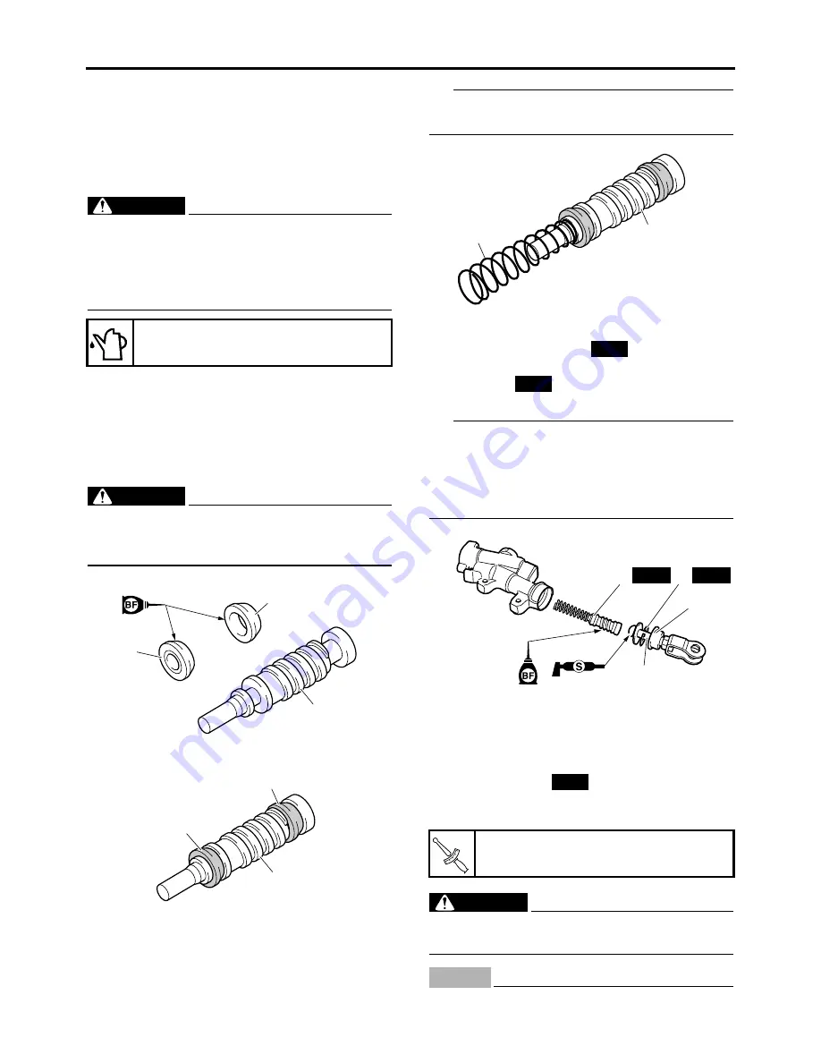
ASSEMBLING THE REAR BRAKE MASTER
CYLINDER
WARNING
EWA13520
• Before installation, all internal brake com-
ponents should be cleaned and lubricated
with clean or new brake fluid.
• Never use solvents on internal brake com-
ponents.
1. Wash the brake master cylinder and the
brake master cylinder kit with brake fluid.
2. Install:
•
Primary cylinder cup “1”
•
Secondary cylinder cup “2”
Install to the brake master cylinder piston “3”.
WARNING
EWA19300
Apply brake fluid to the cylinder cups and in-
stall them as shown. Wrong orientation in in-
stallation causes poor braking performance.
3. Install:
•
Spring “1”
Install to the brake master cylinder piston “2”.
TIP
Install the spring with a smaller inside diameter
to the brake master cylinder piston.
4. Install:
•
Master cylinder kit “1”
•
Push rod “2”
•
Circlip “3”
•
Dust boot “4”
TIP
•
Before installation, apply brake fluid to the
brake master cylinder kit.
•
Before installation, apply silicone grease to the
push rod end.
•
Use circlip pliers to install the circlip.
EAM30051
INSTALLING THE REAR BRAKE MASTER
CYLINDER
1. Install:
•
Copper washer
•
Brake hose
•
Union bolt
WARNING
EWA13531
Proper brake hose routing is essential to in-
sure safe vehicle operation.
NOTICE
ECA24500
Make sure that the pipe portion of the brake
Specified brake fluid
DOT 4
2
3
1
2
3
1
Brake hose union bolt
30 N·m (3.0 kgf·m, 22 lb·ft)
1
2
New
New
1
3
4
2
New
New
New
T
R
.
.
Summary of Contents for YZ 2019 Series
Page 6: ...EAM20162 YAMAHA MOTOR CORPORATION U S A YZ MOTORCYCLE LIMITED WARRANTY...
Page 10: ......
Page 40: ...MOTORCYCLE CARE AND STORAGE 1 28...
Page 63: ...LUBRICATION POINTS AND LUBRICANT TYPES 2 22...
Page 66: ...LUBRICATION SYSTEM CHART AND DIAGRAMS 2 25...
Page 68: ...LUBRICATION SYSTEM CHART AND DIAGRAMS 2 27...
Page 70: ...LUBRICATION SYSTEM CHART AND DIAGRAMS 2 29...
Page 72: ...CABLE ROUTING DIAGRAM 2 31 EAM20152 CABLE ROUTING DIAGRAM...
Page 74: ...CABLE ROUTING DIAGRAM 2 33...
Page 76: ...CABLE ROUTING DIAGRAM 2 35...
Page 78: ...CABLE ROUTING DIAGRAM 2 37...
Page 80: ...CABLE ROUTING DIAGRAM 2 39...
Page 82: ...CABLE ROUTING DIAGRAM 2 41...
Page 84: ...CABLE ROUTING DIAGRAM 2 43...
Page 86: ...CABLE ROUTING DIAGRAM 2 45...
Page 126: ...ELECTRICAL SYSTEM 3 38...
Page 177: ...FRONT FORK 4 49 1...
Page 196: ...CHAIN DRIVE 4 68...
Page 217: ...CAMSHAFT 5 18 Spark plug Spark plug 13 N m 1 3 kgf m 9 6 lb ft T R...
Page 237: ...ELECTRIC STARTER 5 38...
Page 256: ...OIL PUMP AND BALANCER GEAR 5 57 a 2 10 b 2 9 1 b 5 3 a 4 10 5 9 3 E c d 6 7 8 8 b 6...
Page 262: ...GENERATOR AND STARTER CLUTCH 5 63 1 a 3 3 2 4...
Page 276: ...TRANSMISSION 5 77...
Page 284: ...WATER PUMP 6 7...
Page 290: ...FUEL TANK 7 5 A Left B Right 1 1 A 0 mm 0 in B 1 1 15 mm 0 59 in...
Page 296: ...THROTTLE BODY 7 11...
Page 299: ......
Page 313: ...CHARGING SYSTEM 8 14...
Page 343: ...FUEL INJECTION SYSTEM 8 44...
Page 347: ...FUEL PUMP SYSTEM 8 48...
Page 348: ...ELECTRICAL COMPONENTS 8 49 EAM20147 ELECTRICAL COMPONENTS 9 10 1 3 2 4 5 6 7 8...
Page 350: ...ELECTRICAL COMPONENTS 8 51 11 10 9 2 3 1 6 7 8 4 5...
Page 352: ...ELECTRICAL COMPONENTS 8 53 EAM30289 CHECKING THE SWITCHES 4 1 3 2 B B Sb B B B B B B B B...
Page 368: ...ELECTRICAL COMPONENTS 8 69...
Page 376: ...LIST OF SELF DIAGNOSTIC AND FAIL SAFE ACTIONS 9 7...


