6-1
ELECTRICAL COMPONENTS AND WIRING DIAGRAM
ELECTRICAL
This section is intended for those who have basic knowledge and skill concerning the servicing of Yamaha motorcycles
(e.g., Yamaha dealers, service engineers, etc.). Those who have little knowledge and skill concerning servicing are request-
ed not to undertake inspection, adjustment, disassembly, or reassembly only by reference to this manual. It may lead to
servicing trouble and mechanical damage.
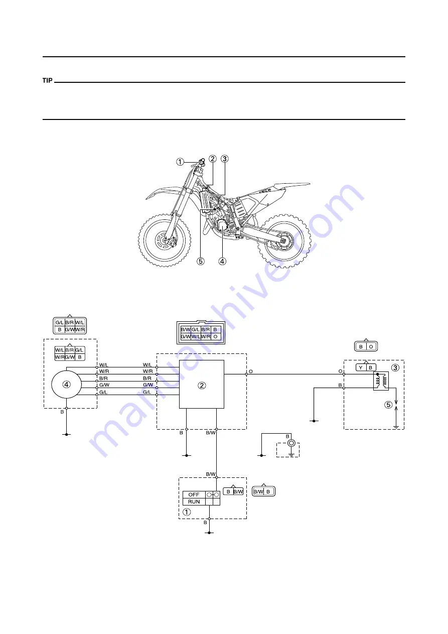
ELECTRICAL COMPONENTS AND WIRING DIAGRAM
ELECTRICAL COMPONENTS
1.
Engine stop switch
2.
CDI unit
3.
Ignition coil
4.
CDI magneto
5.
Spark plug
WIRING DIAGRAM
1.
Engine stop switch
2.
CDI unit
3.
Ignition coil
4.
CDI magneto
5.
Spark plug
COLOR CODE
B
Black
O
Orange
Y
Yellow
B/R
Black/Red
B/W
Black/White
G/L
Green/Blue
G/W
Green/White
W/L
White/Blue
W/R
White/Red
Summary of Contents for YZ125 2016
Page 4: ......
Page 12: ...1 2 LOCATION OF IMPORTANT LABELS EUROPE...
Page 13: ...1 3 LOCATION OF IMPORTANT LABELS AUS NZ ZA...
Page 61: ...3 18 CHASSIS...
Page 165: ......
Page 166: ...PRINTED IN JAPAN E PRINTED ON RECYCLED PAPER...


