4-27
KICK SHAFT AND SHIFT SHAFT
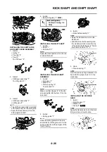
INSTALLING THE PRIMARY DRIVE
GEAR
1. Install:
• Spacer "1"
• Primary drive gear "2"
• Bolt "3"
Install the primary drive gear with its
depressed side toward you.
2. Install:
• Primary driven gear
Refer to "CLUTCH" section.
3. Tighten:
• Bolt (primary drive gear) "1"
Place an aluminum plate "a" between
the teeth of the primary drive gear
and driven gear.
4. Install:
• Dowel pin "1"
• Gasket [crankcase cover (right)]
"2"
5. Install:
• Crankcase cover (right) "1"
Mesh the governor gear "2", and im-
peller shaft gear "3" with primary
drive gear "4".
6. Install:
• Bolt [crankcase cover (right)] "1"
Tighten the bolts in stage, using a
crisscross pattern.
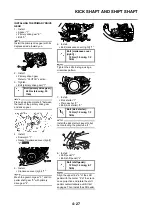
7. Install:
• Kick starter "1"
• Plain washer "2"
• Bolt (kick starter) "3"
Install the kick starter closest to but
not contacting the pillar tube "4".
8. Install:
• Shift pedal "1"
• Bolt (shift pedal) "2"
Align the upper line "a" of the shift
pedal with the center "b" of the crank-
case projection and rotate the shift
pedal counterclockwise until it first
engages. Then install the shift pedal.
Bolt (primary drive gear):
48 Nm (4.8 m•kg, 35
ft•lb)
Bolt [crankcase cover
(right)] :
10 Nm (1.0 m•kg, 7.2
ft•lb)
Bolt (kick starter) :
10 Nm (1.0 m•kg, 7.2
ft•lb)
Bolt (shift pedal) :
12 Nm (1.2 m•kg, 8.7
ft•lb)
Summary of Contents for YZ125X1
Page 2: ...1C3 9 33_cover 07 6 14 9 59 AM Page 2...
Page 3: ...YZ125 X X1 1C3 28199 33 E0 2008 OWNER S SERVICE MANUAL...
Page 4: ......
Page 87: ...4 32 WATER PUMP...
Page 131: ...5 30 STEERING 9 Bearing race 2 Refer to removal section Order Part name Q ty Remarks...
Page 159: ......


