4-20
CYLINDER HEAD
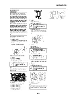
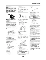
CHECKING THE CYLINDER HEAD
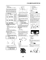
1. Eliminate:
• Carbon deposits (from the com-
bustion chambers)
Use a rounded scraper.
Do not use a sharp instrument to
avoid damaging or scratching:
• Spark plug threads
• Valve seats
2. Inspect:
• Cylinder head
Scratches/damage
→
Replace.
3. Measure:
• Cylinder head warpage
Out of specification
→
Resurface.
Warpage measurement and resur-
facing steps:
a. Place a straightedge and a feeler
gauge across the cylinder head.
b. Use a feeler gauge to measure
the warpage.
c. If the warpage is out of specifica-
tion, resurface the cylinder head.
d. Place a 400–600 grit wet sandpa-
per on the surface plate, and re-
surface the head using a figure-
eight sanding pattern.
To ensure an even surface rotate the
cylinder head several times.
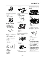
INSTALLING THE CYLINDER
HEAD
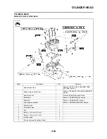
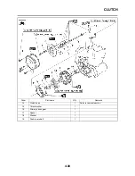
1. Install:
• Dowel pin "1"
• Cylinder head gasket "2"
• Timing chain guide (exhaust side)
"3"
• Cylinder head "4"
While pulling up the timing chain, in-
stall the timing chain guide (exhaust
side) and cylinder head.
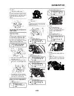
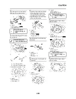
2. Install:
• Washer "1"
• Cable guide "2"
• Bolts [L = 145 mm (5.71 in)] "3"
• Bolts [L = 135 mm (5.31 in)] "4"
• Nuts "5"
• Apply the molybdenum disulfide
grease on the thread and contact
surface of the bolts.
• Follow the numerical order shown
in the illustration. Tighten the bolts
and nuts in two stages.
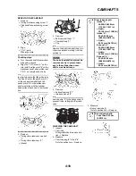
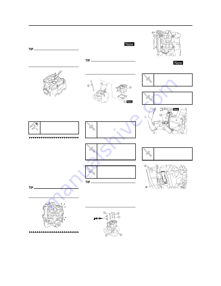
3. Install:
• Copper washer "1"
• Oil delivery pipe "2"
• Union bolt (M8) "3"
• Union bolt (M10) "4"
4. Install:
• Radiator pipe "1"
• Bolt (radiator pipe) "2"
Cylinder head warpage:
Less than 0.05 mm
(0.002 in)
Bolts [L = 145 mm (5.71
in)]:
38 Nm (3.8 m•kg, 27
ft•lb)
Bolts [L = 135 mm (5.31
in)]:
38 Nm (3.8 m•kg, 27
ft•lb)
Nuts:
10 Nm (1.0 m•kg, 7.2
ft•lb)
Union bolt (M8):
18 Nm (1.8 m•kg, 13
ft•lb)
Union bolt (M10):
20 Nm (2.0 m•kg, 14
ft•lb)
Bolt (radiator pipe):
10 Nm (1.0 m•kg, 7.2
ft•lb)

