CRANKSHAFT
5-79
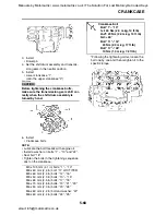
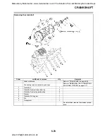
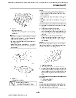
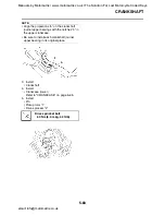
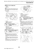
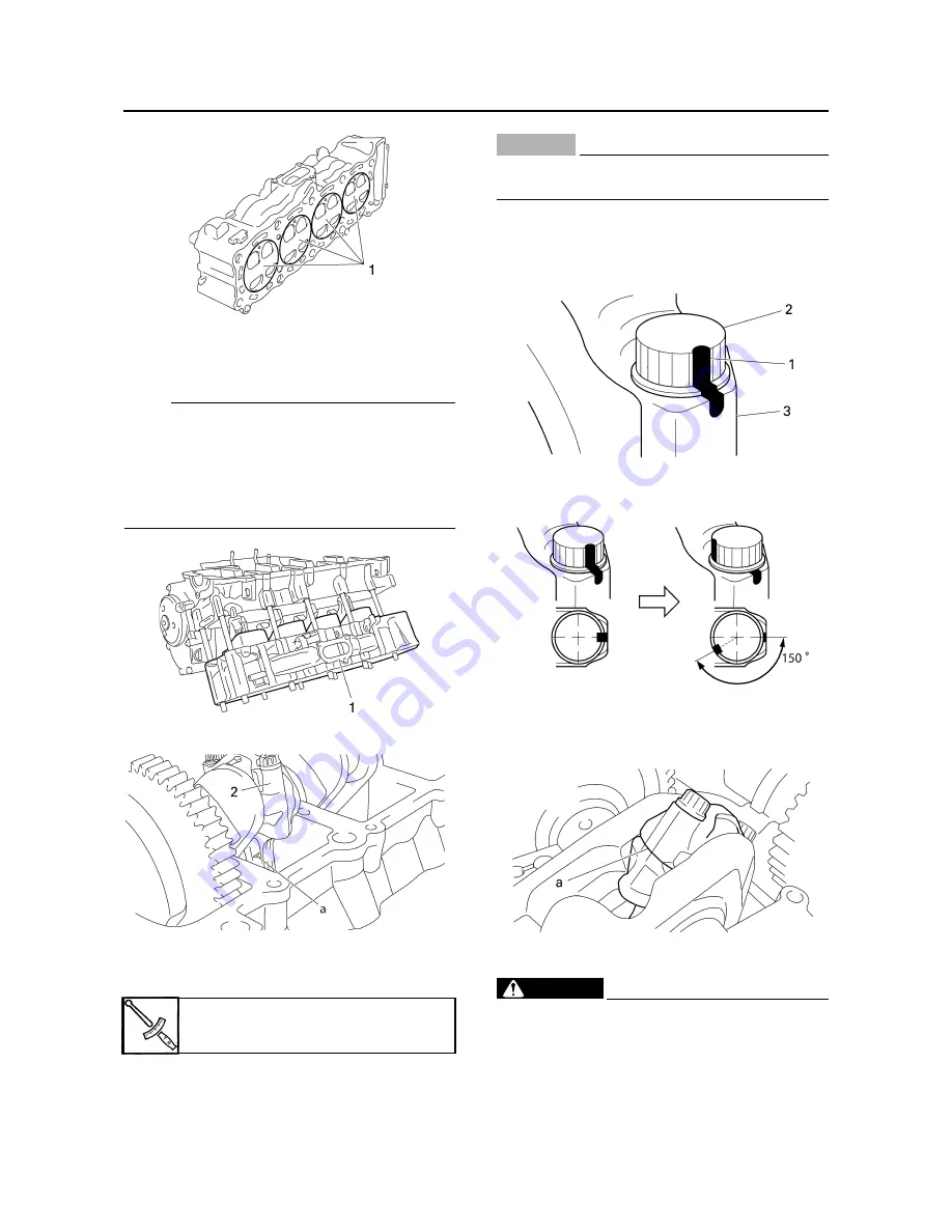
11. Install:
• Cylinder assembly “1”
• Connecting rod caps “2”
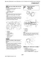
NOTE:
• Make sure that the “Y” marks “a” on the con-
necting rods face towards the left side of the
crankshaft.
• Make sure that the characters on both the
connecting rod and connecting rod cap are
aligned.
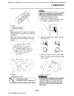
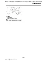
12. Tighten:
• Connecting rod bolts
▼▼▼▼▼▼▼▼▼▼▼▼▼▼▼▼▼▼▼▼▼▼▼▼▼▼▼▼▼▼
CAUTION:
ECA14980
Tighten the connecting rod bolts using the
plastic-region tightening angle method.
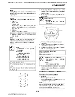
a. Clean the connecting rod bolts.
b. Tighten the connecting rod bolts.
c. Put a mark “1” on the connecting rod bolt
“2” and the connecting rod cap “3”.
d. Tighten the bolt further to reach the speci-
fied angle (150
°
).
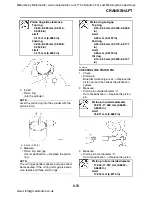
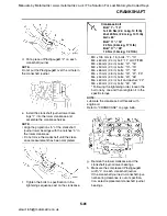
e. After the installation, check that the section
shown “a” is flush with each other by touch-
ing the surface.
WARNING
EWA13990
• When the bolt is tightened more than the
specified angle, do not loosen the bolt
and then retighten it. Replace the bolt
with a new one and perform the proce-
dure again.
Connecting rod bolt
20 Nm (2.0 m·kg, 14 ft·lb)+150
°
a. Side machined face
Manuals by Motomatrix / www.motomatrix.co.uk / The Solution For Lost Motorcycle Coded Keys
email: info@motomatrix.co.uk

