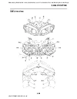
CABLE ROUTING
2-48
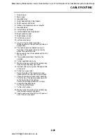
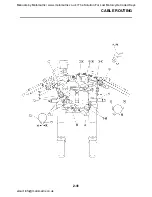
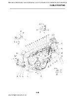
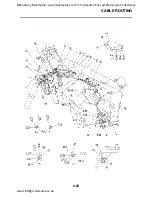
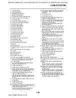
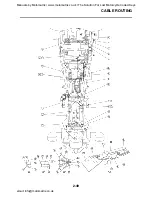
1. Throttle cables
2. Rectifier/regulator
3. Rectifier/regulator lead
4. Right air outlet grille
5. Air induction system solenoid hose
6. Intake funnel servo motor lead
7. O
2
sensor lead
8. Rear brake light switch lead
9. Crankshaft position sensor lead
10.Engine ground lead
11.Battery negative lead
12.Neutral switch lead
13.Speed sensor lead
14.Oil level switch lead
15.Sidestand switch lead
16.Fuel tank drain hose
17.AC magneto lead
18.Pulley cover rib
19.Atmospheric pressure sensor
20.Immobilizer lead
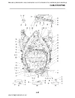
21.Left air outlet grille
22.Left radiator fan motor lead
23.Cover 2
24.Wire harness
25.Throttle position sensor (for throttle valves)
lead
26.Atmospheric pressure sensor lead
27.Frame
28.Locating damper
29.Throttle body
30.Connector housing
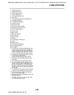
A. To the right handlebar switch lead.
B. Pass it so that there is no torsion through
the clamp which inserted to the cover.
C. To the engine
D. Pass the rectifier/regulator lead through
the notch hole of the cover.
E. To the throttle body
F. To the intake funnel servo motor
G. Intake funnel servo motor lead should be
routed by the front and outer side than the
air induction system solenoid hose.
H. Clamp the wire harness winding in and
insert it to the frame hole.
I. After connecting the coupler, make sure to
insert it between the delivery pipe and ther-
mostat.
J. For routing the fuel hoses, refer to the fuel
tank section.
K. To the starter motor
L. To the air filter case
M. Point the tip of the clamp (cut the tip of the
clamp leaving 2 to 4 mm (0.08 to 0.16 in).)
to the inside of the vehicle.
Fasten the wire harness and crankshaft
position sensor lead with a clamp.
N. All hoses and leads should be routed over
the vehicle’s upper side above the heat
protector.
O. To the fuel pump
P. To the speed sensor
Q. Clamp the wire harness winding in and
insert it to the frame hole.
R. Install the leads so that the engine ground
lead is positioned lower and the battery
negative lead to be upper.
Install the protrusion of each lead to be
above the vehicle.
S. It should not be positioned on the harness.
T. Route it under the wire harness, speed
sensor lead, O
2
sensor lead and rear brake
light switch lead.
U. Point the tip of the clamp (cut the tip of the
clamp leaving 2 to 4 mm (0.08 to 0.16 in).)
to the inside of the vehicle.
Fasten the wire harness, oil level switch
lead and sidestand switch lead with a
clamp.
V. Align the clamp position with the taping
sections
Point the tip of the clamp (cut the tip of the
clamp leaving 2 to 4 mm (0.08 to 0.16 in).)
to the upper side of the vehicle.
Fasten the AC magneto lead with a clamp.
W. Route the AC magneto lead by the outside
of the pulley cover rib.
X. Clamp the wire harness winding in and
insert it to the frame hole.
Y. Pass the AC magneto lead through the
notch hole of the cover 2.
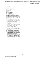
Z. To the throttle cable lever
AA.To the radiator
AB.Clamp the AC magneto lead.
AC.To the throttle position sensor (for throttle
valves)
AD.Route each lead lower than the frame
plate.
Leads should be routed in random order.
Clamp can be inserted in any direction.
AE.Route each lead higher than the frame
plate, pass it to the inside of the vehicle
from the hole.
Leads should be routed in random order.
Clamp can be inserted in any direction.
AF.Fit the immobilizer lead coupler into the
connector housing with its projection posi-
tioned as shown in the illustration, and then
install the holder onto the cover 2.
Manuals by Motomatrix / www.motomatrix.co.uk / The Solution For Lost Motorcycle Coded Keys
email: info@motomatrix.co.uk

