background image

Summary of Contents for YZF-R1

Page 1: ......

Page 2: ...without notice for improvement Parts List Symbols The star mark means that the part is included in the kit set and is a genuine Yamaha part Therefore you can easily purchase the part at any Yamaha pa...

Page 3: ...plug Set 2CR A4890 70 35 17 Transmission Gear 36 18 Mission Maintenance Set 2CR A7000 70 39 19 Drive Sprockets 42 20 Sprocket Nut Set 2CR A7463 70 43 21 Strainer Cover Set 2CR 13400 71 44 2 3 Installi...

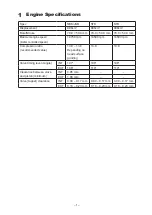
Page 4: ...rolled speed 14750 rpm 14500 rpm 14500 rpm Compression ratio recommended value 13 0 13 4 Depending on head surface grinding 13 0 13 0 Valve timing event angle INT 107 108 108 EXT 106 110 110 Clearance...

Page 5: ...e please write SBK base data R1 20 _BaseData _ 00 _ SBK ycz with FI matching system SBK control data is for modified engine When using it with STK please remove the 2 pole coupler of the kit harness l...

Page 6: ...MGC 191114 00 2CR 8591A 70 2CR F2590 70 R1 2CR 83500 00 SET No 2CR 28130 70 R1M 2KS 83500 00 2KS 28130 70 2016 2CR 1440B 70 2CR 8591A 71 2CR 8591A 72 2017 2018 2019 2CR 12170 70 2CR 12180 70 2CR A211...

Page 7: ...e ECU is equipped with a self diagnostic function in order to ensure that the fuel injection system is operating normally If this function detects a malfunction in the system it immediately operates t...

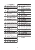
Page 8: ...ow Bank 1 or Single Sensor P0343 Camshaft Position Sensor A Circuit High Bank 1 or Single Sensor P0351 Ignition Coil A Primary Control Circuit Open P0352 Ignition Coil B Primary Control Circuit Open P...

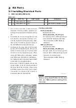
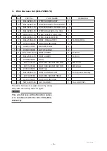
Page 9: ...5 2CR 8231Y 70 WIRE LEAD for FUEL PUMP 1 6 B3L 83553 70 WIRE LEAD for METER 1 7 B3L 2128A 70 BRKT REGULATOR 1 1 For REC REG 8 92017 06020 BOLT BUTTON HEAD 2 9 90201 07081 WASHER PLAIN 2 10 95607 0620...

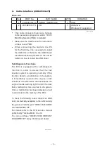
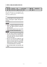
Page 10: ...isassemble the Hydraulic unit assy TIP If the E SD STD steering damper is not used removing its coupler will pose no problem No PART No PART NAME Q TY REMARKS 21 2KS 82509 70 WIRE SUB LEAD 1 SCU 4 WIR...

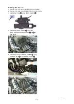
Page 11: ...e the side cover bracket left from the vehicle 3 Install the PLUG13 to the BRKT UNDER12 M6 16mm M6 20mm 4 Install the BRKT UNDER12 using the BOLT HEX SOCKER BUTTON 14 and15 to the frame 5 Install the...

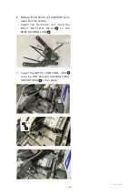
Page 12: ...rom the vehicle Install the Hydraulic unit using the B O LT B U T T O N H E A D 19 t o t h e BRKT CONTROL UNIT17 Hydraulic unit 7 Install the BRKT CONTROL UNIT 17 using the STD Bolt and collar BOLT HE...

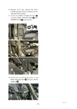
Page 13: ...ULATOR 1 7 using the NUT U FLANGE 10 8 Remove from the chassis the STD rectifier regulator that is installed on the right side of the radiator 9 Install the BRK T REGUL ATOR 1 7 using the BOLT BUTTON...

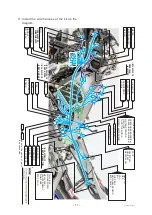
Page 14: ...70 BRKT UNDER B3L 2128A 70 BRKT REGULATOR1 METER AC INJECTOR TH INJECTOR REC REGU FUEL PUMP PC I F SELECT SW LIGHT SW NEUTRAL SW ABS ECU OBD CCU IMU FUSE BOX RR WHEEL SENSOR BTRY MINUS TAIL LIGHT POW...

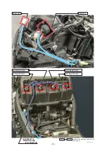
Page 15: ...12 METER MAIN SW AC INJECTOR 2 AC INJECTOR 1 AC INJECTOR 3 AC INJECTOR 4 B3L 82318 70 WIRE SUB LEAD for AC INJECTOR indicate the names of parts to be connected R1 EN2911 2019Rev...

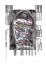
Page 16: ...SENSOR STD SUB LEAD for WATER TEMP SENSOR SELECT SW AC INJECTOR B3L 82309 70 WIRE SUB LEAD for IG COIL PC I F FUEL PUMP 2CR 8231Y 70 WIRE LEAD NEUTRAL SW LIGHT SW REC REGU VI MOTOR AIR TEMP SENSOR IG...

Page 17: ...LAP switch Keep the switch at low position Hi position the LAP switch becomes non functional Pit road limiter ON ON PUSH OFF Not used Mode switch Up button Center button Down button MAP SELECT MAP 1 M...

Page 18: ...in the forward backward up down and right left directions YRC controls the engine output based on data received from those sensors PWR Power Delivery Mode The power mode selection system consists of f...

Page 19: ...the sensor on the shift rod detects the appropriate motion in the shift pedal engine power output is momentarily adjusted to allow for the gear change to occur LIF Lift control system The lift contro...

Page 20: ...netic properties 2 Make the angle of attachment in the rotation direction of the rotor of the sensor assembly the same as the angle indicated in the diagram below 3 If you change the rotor sensor or s...

Page 21: ...dlights and taillights are used There are three light switches SW 1 Turns on the headlight high beam and taillight 1 SW 2 Turns on the headlight low beam and taillight 2 EMERGENCY SW Turns on the emer...

Page 22: ...Q TY REMARKS 1 2CR 83500 00 METER ASSY 1 2 2CR 83963 00 SWITCH HANDLE 3 1 3 2CR 83969 00 SWITCH HANDLE 5 1 4 2CR 85970 00 FR WHEEL SENSOR 1 5 2CR 85980 00 RR WHEEL SENSOR 1 Parts List 2CR 28130 70 fo...

Page 23: ...ER ASSY 1 2 2CR 83963 00 SWITCH HANDLE 3 1 3 2CR 83969 00 SWITCH HANDLE 5 1 4 2CR 85970 00 FR WHEEL SENSOR 1 5 2CR 85980 00 RR WHEEL SENSOR 1 Parts List 2KS 28130 80 for 2018 2019 YZF R1M 2KS BAF No P...

Page 24: ...ition to this manual R1 EN2911 2019Rev Parts List No PART No PART NAME Q TY REMARKS 1 2KS 85810 72 CCU ASSY 1 dedicated software embedded 2 2KS 88107 00 GPS unit 1 3 2KS 85721 71 Sub harness 1 Applica...

Page 25: ...RIP 2 1234 5 km 1 N 2 km h 1000 r min MODE A PWR 1 TCS 1 SCS 1 A 1 LCS QS LIF GPS 12 00 Since the GPS and oil pressure warning icons are at the same location the GPS icon does not light up when the th...

Page 26: ...ack See Fig 2 CCU Config Y TRAC for iOS version CCU While riding After riding Download the logging data from the CCU Y TRAC CCU Display the logging data with map Y TRAC Internet Usage Fig 1 Fig 2 TIP...

Page 27: ...specification of the installed sensor To change the display value tap AIN Setting Example 1 When the following is stated in the sensor s manual AF value voltage x 1 6 10 Factor 1 6000 Offset 10 0000...

Page 28: ...TEST 40 03 06 1000 r min A 2 QS LIF GPS 12 00 ABERAGE 2 1 Wheel switch operation procedure Press the wheel switch to blink area 1 Rotate the wheel switch to blink area 2 Press and hold the wheel switc...

Page 29: ...2 24 INT 7 4TE 12119 00 SEAL VALVE STEM OIL 24 EXT 8 BX4 13414 00 GASKET STRAINER 3 OIL PAN 9 2CR 15451 70 GSKT CRANKCASE COVER 1 3 CLUTCH 10 2CR 15461 70 GSKT CRANKCASE COVER 2 3 CLUTCH 11 2CR 15456...

Page 30: ...is of a semi surface discharge type of shape TIP Since these spark plugs have a copper gasket caution is needed during installation on the following points 1 The tightening torque is 12 15 N m 1 2 1 5...

Page 31: ...eed 0 5 g 11 Connecting Rod Set 2CR 1165B 70 Parts List No PART No PART NAME Q TY REMARKS 1 2CR 11650 00 CONN ROD ASSY 1 4 This set consists of four genuine connecting rod assemblies and the weight di...

Page 32: ...s piston rings and piston pins the set enables installing those items on any model year engine at once Connecting rod No change Crankshaft As a thrust bearing is added to the 4 cylinder for the 2016 t...

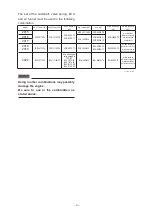
Page 33: ...of the camshaft valve spring ECU and air funnel must be used in the following combination Use the Valve spring of the STD 14 Cam Sprocket B3L 12176 70 No PART No PART NAME Q TY REMARKS 1 B3L 12170 70...

Page 34: ...83500 00 SET No 2CR 28130 70 R1M 2KS 83500 00 2KS 28130 70 2016 2CR 1440B 70 2CR 8591A 71 2CR 8591A 72 2017 2018 2019 2CR 12170 70 2CR 12180 70 2CR A2110 71 2CR 1440B 70 BX4 8591A 70 BX4 8591A 71 BX4...

Page 35: ...ion to combine the camshaft and cylinder head surface 2 Adjust the valve timing to the value stated on the normal specifications using the long holes How to position at 1 cylinder s compression top de...

Page 36: ...ns Ycci System Control You can use the Ycci system as the kit funnel You can control the operation timing by using the YMS software packed together with the kit ECU You can also control the STD funnel...

Page 37: ...1 MGC 191114 00 2CR 8591A 70 2CR F2590 70 R1 2CR 83500 00 SET No 2CR 28130 70 R1M 2KS 83500 00 2KS 28130 70 2016 2CR 1440B 70 2CR 8591A 71 2CR 8591A 72 2017 2018 2019 2CR 12170 70 2CR 12180 70 2CR A21...

Page 38: ...lve accompanying the hose 2 Remove the cap fitted to the hose remove the reed valve and plate from inside 3 Install the 1 PLATE 2 5SL 1482L 70 in replacement of the cap Be sure to apply liquid gasket...

Page 39: ...80 GEAR 5TH PINION B 1 6 2CR 17161 70 GEAR 6TH PINION A 1 7 2CR 17161 80 GEAR 6TH PINION B 1 8 2CR 17402 00 DRIVE AXLE ASSY 1 9 2CR 17211 70 GEAR 1ST WHEEL 1 10 2CR 17221 70 GEAR 2ND WHEEL 1 11 2CR 17...

Page 40: ...se combine standard gear Gear ratio STD KIT 1st 39 15 2 600 39 16 2 438 2nd 37 17 2 176 35 17 2 059 3rd 35 19 1 842 34 19 1 789 4th 30 19 1 579 33 21 1 571 5th A 29 21 1 381 32 22 1 455 5th B 31 22 1...

Page 41: ...68 3 264 1 263 2 262 4 KIT B 25 33 1 32 328 2 319 8 311 8 307 7 304 2 299 8 296 9 292 3 290 0 287 2 285 1 283 4 279 8 278 4 277 1 272 8 271 9 271 1 GEAR PLAN The number of teeth Ratio 14 15 16 16 15 1...

Page 42: ...4 25003 WASHER CLAW 3 27 90387 31003 COLLAR 3 28 90209 28008 WASHER 9 29 93440 31187 CIRCLIP 9 30 90387 28004 COLLAR 6 31 90214 29002 WASHER CLAW 3 32 90214 28002 WASHER CLAW 3 33 90387 25008 COLLAR 3...

Page 43: ...40 36 38 33 29 29 34 21 22 22 24 23 23 35 25 26 37 28 30 32 31 30 28 28 29 27...

Page 44: ...pline threads Circlip Shaft Edge PortionR Edge Detail of installation of washer Detail of installation of washer Shaft Washer Washer Matching mark Matching mark Portion R Washer Gear The seal side sho...

Page 45: ...PART NAME Q TY REMARKS 1 2CR 17460 74 SPROCKET DRIVE 1 14T 520SIZE 2 2CR 17460 75 SPROCKET DRIVE 1 15T 520SIZE 3 2CR 17460 76 SPROCKET DRIVE 1 16T 520SIZE This sprocket is weight saved by changing the...

Page 46: ...3 20 Sprocket Nut Set 2CR A7463 70 Parts List No PART No PART NAME Q TY REMARKS 1 90179 22018 NUT 3 2 90208 22002 WASHER CONICAL SPRG 3 The OUT mark must face outward Apply swage after tightening a nu...

Page 47: ...72 BOLT HEX SOCKET 2 1 attachment 6 2CR 13418 70 PIPE OIL 2 1 7 2CR 13416 71 PIPE OIL 1 1 8 93210 14003 O RING 3 6 7 attachment Grease outer surface 9 90110 06393 BOLT HEX SOCKET 1 6 attachment 10 901...

Page 48: ...IPE OIL 1 and 23 BRKT STRAINER 1 to the engine by using 8 O RING and 10 BOLT HEX SOCKET tighten 7 PIPE OIL 1 together with 23 BRKT STRAINER 1 3 4 2 6 23 7 TIP Visually confirm the condition of 6 PIPE...

Page 49: ...15 PAN OIL by using 21 BOLT 21 21 21 620 620 LT 620 20 15 6 Fix 1 STRAINER HSG ASSY 11 PIPE DELIVERY 1 and 23 BRKT STRAINER 1 by u s i n g 12 G RO M M E T 13 COLLAR DISTANCE 14 BOLT and 22 WASHER PLA...

Page 50: ...47 8 Attach 15 PAN OIL to the engine by using 16 BOLT BUTTON HEAD 15 9 Attach 17 PLUG STRAIGHT SCREW and 18 GASKET to 15 PAN OIL 17 18 TIP Be sure to check the torque when installing...

Page 51: ...and check that the oil level is within a range of the upper limit of the oil pan window right side of the vehicle to the lower limit of the engine crank case oil window left side of vehicle If it is o...

Page 52: ...4 2CR 22222 80 SPRG REAR SHOCK 1 103 N mm Identifying stamp 159 5 56 103 5 2CR 22222 85 SPRG REAR SHOCK 1 108 N mm Identifying stamp 159 5 56 108 There is a stamp on the side of the springs for rate i...

Page 53: ...spring for rate identification Free lengths are STD spring andKIT spring 219 5mm The spring rate of the STD is 9 0 N mm For information about spring replacement see STD Service Manual R1 EN2911 2019R...

Page 54: ...ke displacement depending on conditions Braking Load change The harder the brake is applied the more the load is concentrated on the front Front fork Displaces until stroke has almost bottomed Rear cu...

Page 55: ...52 24 Seat Cushion 13S 24713 70 Parts List No PART No PART NAME Q TY REMARKS 1 13S 24713 70 CUSHION SEAT 1 Anti slip seat Cut to any size for use...

Page 56: ...EMARKS 1 2CR 25160 00 CAST WHEEL ASSY 1 2 93900 00030 VALVE RIM 1 3 1SD 2517G 00 ROTOR SENSOR 1 4 2CR 2514A 00 RING WHEEL 1 1 5 90149 05037 SCREW 5 6 93210 47440 O RING 1 This kit does not include a t...

Page 57: ...MARKS 1 B3L 25370 00 CAST WHEEL ASSY 1 2 B3L 25840 00 DISK BRAKE ASSY 1 3 90111 08085 BOLT HEX SOCKET BUTTON 5 4 93900 00030 VALVE RIM 1 This kit does not include a tire This part is the STD wheel bea...

Page 58: ...3L 12180 73 Rr SPROCKET 42T 1 6 B3L 12180 74 Rr SPROCKET 43T 1 7 B3L 12180 75 Rr SPROCKET 44T 1 8 B3L 12180 76 Rr SPROCKET 45T 1 9 B3L 12180 77 Rr SPROCKET 46T 1 10 B3L 12180 78 Rr SPROCKET 47T 1 11 B...

Page 59: ...perating angle of the throttle grip when the throttle is fully opened is 57 5 as against STD 67 Except this part all other parts should be STD parts 57 5 67 Throttle grip operation angle 20 KIT specif...

Page 60: ...AD M6 1 0 8 5 1 5 0 85 0 15 2 CAP x HEAD 90105 06027 BOLT FLANGE M6 x 1 0 When using the bolt continuously Apply oil to the bearing surface and thread part of the bolt and tighten with tightening torq...

Page 61: ...ck that the final tightening torque is 40 0 to 85 0 N m 4 0 to 8 5 kgf m If not replace the bolt with new one and re tight it again 8 each Do not leave EG oil or grease on the bearing sur face or thre...

Page 62: ...0 2 1 Tighten DRAIN BOLT 90340 14019 PLUG STRAIGHT SCREW M14 x 1 5 23 2 4 3 0 4 1 Install PIPE OIL 1 90110 06182 BOLT HEXAGON SOCKET HEAD M6 x 1 0 10 2 1 0 0 2 2 APPLY TO SCREW ROCKING Install HOUSIN...

Page 63: ...OLT HEXAGON SOCKET HEAD M6 x 1 0 10 2 1 0 0 2 2 APPLY TO SCREW ROCKING Tighten the cover side of OIL PIPE COMP 2 90110 06295 BOLT HEXAGON SOCKET HEAD M6 x 1 0 10 2 1 0 0 2 1 APPLY TO SCREW ROCKING Ins...

Page 64: ...KET M6 x 1 0 10 2 1 0 0 2 1 SILENCER x STAY MUFFLER3 90110 08071 BOLT HEXAGON SOCKET M8 x 1 25 20 2 2 0 0 2 1 Install WIRE PULLEY DOUBLE NUT 2CR 1133E oo WIRE PULLEY 1 M6 x 1 0 5 7 0 5 0 7 2 2CR 1133F...

Page 65: ...2 90105 06213 BOLT M6 x 1 0 10 2 1 0 0 2 2 APPLY TO SCREW ROCKING APPLY OIL TO THE BEARING SURFACE ONLY CRANKCASE 1 x CRANKCASE 2 95812 06040 BOLT FLANGE M6 x 1 0 10 2 1 0 0 2 5 APPLY OIL TO BOTH SCRE...

Page 66: ...4H7 15189 00 PLUG M20 x 1 5 8 2 0 8 0 2 2 TAKE CARE NOT TO OVERTIGHTEN Install CLUTCH WIRE HOLDER 90110 06340 BOLT M6 x 1 0 10 2 1 0 0 2 2 APPLY TO SCREW ROCKING ACM LEAD 90110 06182 BOLT HEXAGON SOCK...

Page 67: ...CREW M6 x 1 0 10 2 1 0 0 2 2 APPLY TO SCREW ROCKING Install STOPPER SCREW 1D7 18127 00 STOPPER SCREW M8 x 1 25 22 2 2 2 0 2 1 APPLY TO SCREW ROCKING Install ARM SHIFT 90105 06127 BOLT FLANGE M6 x 1 0...

Page 68: ...2 APPLY TO SCREW ROCKING OIL PRESSURE SWITCH 1WS 82504 00 SW OIL PRESSURE PT1 8 12 5 2 1 25 0 2 1 When mended use 67F 82504 00 and apply the sealing agent to the thread part ThreeBond MEC 2403 Install...

Page 69: ...GON SOCKET M12 x 1 25 50 62 5 0 6 2 1 PROCEDURE TO INSTALL THE ENGINE FOR DETAILS SEE page 74 90179 12004 NUT ADJUST BOLT for E G BRACKET REAR 5YU 21495 00 BOLT ENGINE ADJUSTING M18 x 1 0 7 9 0 7 0 9...

Page 70: ...90109 12010 BOLT M10 x 1 25 31 49 3 1 4 9 1 92902 12600 WASHER PLAIN 90185 12011 NUT SELF LOCKING REAR CUSHION ARM RELAY 90105 10017 BOLT FLANGE M10 x 1 25 31 49 3 1 4 9 1 95602 10200 NUT U FLANGE REA...

Page 71: ...5 1 REAR STAY for FUEL TANK REAR FRAME 90111 06071 BOLT HEXAGON SOCKET BUTTON M6 x 1 0 5 8 0 5 0 8 4 REAR STAY for FUEL TANK FUEL TANK 95812 06090 BOLT FLANGE M6 x 1 0 3 5 0 3 0 5 1 95702 06500 NUT F...

Page 72: ...69 For reference Tightening torque N m M5 0 8 4 5 7 0 M6 1 0 7 5 12 M8 1 25 18 28 M10 1 25 37 58 M12 1 25 68 108 M14 1 5 105 167...

Page 73: ...ening of 45 N m 4 5 kgf m 4 In the following order 1 10 loosen each bolt Then tighten at 15 N m 1 5 kgf m and tighten at rotating angle of 160 Note Do not loosen all bolts at once Repeat loosening and...

Page 74: ...the tightening sequence of 11 to 20 to 24 2 N m 2 4 0 2 kgf m 5 Tighten the bolts in the tightening sequence of 21 to 40 to 10 2 N m 1 0 0 2 kgf m 6 8 7 5 2 4 3 1 22 32 40 12 23 33 13 24 34 14 25 35 1...

Page 75: ...0 3 kgf m and apply snap and angle tightening at rotating angle of 90 Note Do not loosen all bolts at once Repeat loosening and tightening operation one by one bolt TIP The numbers 1 to 12 show the se...

Page 76: ...T HEXAGON SOCKET M6 x 1 0 12 2 1 2 0 2 12 APPLY TO SCREW ROCKING STRAINER COVER Install COVER CRANK CASE 1 15411 90110 06387 BOLT HEXAGON SOCKET M6 x 1 0 12 2 1 2 0 2 8 ACM COVER Install COVER CRANK C...

Page 77: ...attach the bolt 7 temporarily 5 Tighten the two engine adjusting bolts 1 at specified torque Check that the bearing surface of the bolts 1 completely fit the surface of the engine 6 Tighten the two n...

Page 78: ...3 Tighten the nut 3 self rocking at specified torque Be sure to secure the pivot shaft 1 so that it is not co rotated TIP For information about tightening torque and requirement for lubricant agent s...

Page 79: ...76 4 Headlight Cord Wiring Diagram...

Page 80: ...77 5 YZF R1 Wiring Diagram...

Page 81: ...M A I N _ H A R N E S S CCU1_SUB_LEAD L B L W B W R G M A I N _ H A R N E S S WIRE_SUB_LEAD_11 WT B L G W RELAY_ASSY Br W R W R L L R L W R W BLACK ECU2 R W Y B L L Y L G W W B B G B B Y B B L BLACK E...

Page 82: ...Published by YAMAHA MOTOR ENGINEERING co LTD...

Reviews: