PERIODIC MAINTENANCE AND ADJUSTMENT
7-42
7
8. Retighten pinch bolt B to the spec-
ified torque.
9. Tap the outer side of the right fork
leg with a rubber mallet to align it
with the end of the wheel axle.
10. Tighten wheel axle pinch bolt D,
then pinch bolt C to the specified
torque.
11. Retighten pinch bolt D to the spec-
ified torque.
12. While applying the front brake,
push down hard on the handlebar
several times to check for proper
fork operation.
EAU25080
Rear wheel
EAU44951
To remove the rear wheel
WARNING
EWA10821
To avoid injury, securely support the
vehicle so there is no danger of it
falling over.
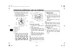
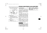
1. Loosen the axle nut.
2. Lift the rear wheel off the ground
according to the procedure on
page 7-40.
3. Remove the axle nut.
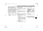
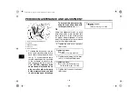
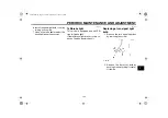
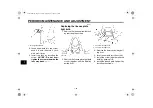
1. Front wheel axle pinch bolt A
2. Front wheel axle pinch bolt B
3. Front wheel axle pinch bolt C
4. Front wheel axle pinch bolt D
Tightening torque:
Wheel axle pinch bolt:
21 Nm (2.1 m·kgf, 15 ft·lbf)
Tightening torque:
Wheel axle pinch bolt:
21 Nm (2.1 m·kgf, 15 ft·lbf)
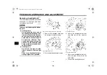
1. Axle nut
2. Drive chain slack adjusting bolt
3. Locknut
4. Brake caliper
5. Brake caliper bracket
U13S12E0.book Page 42 Tuesday, September 15, 2009 1:52 PM

