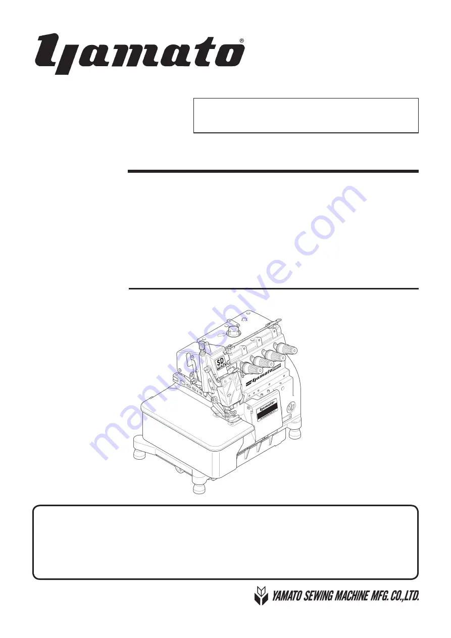
background image

Instruction Manual

SUPPER HIGH SPEED OVERLOCK MACHINE  

SUPPER HIGH SPEED SAFETY STITCH MACHINE

AZ7000SDR-8

 class

AZ7000SDR-8,AZ7003SDR-8,AZ7016SDR-8

AZ7020SDR-8,AZ7025SDR-8,AZ7120SDR-8,AZ7125SDR-8 

AZ7500SDR-8

 class

AZ7500SDR-8,AZ7520SDR-8,AZ7525SDR-8

AZ7500SDR-31,AZ7520SDR-31,AZR7525SDR-31

Thank  you  for  purchasing  the  AZ7000SDR-8  and  AZ7500SDR-8  class.  Before  using  your 
AZ7000SDR-8 and AZ7500SDR-8 class, please read the instruction manual and understand 
the contents well. 
After reading the instruction manual, please keep it in a location where it is easily accessible 
to the operator.

Summary of Contents for AZ7000SDR-8

Page 1: ...DR 8 AZ7500SDR 8 class AZ7500SDR 8 AZ7520SDR 8 AZ7525SDR 8 AZ7500SDR 31 AZ7520SDR 31 AZR7525SDR 31 Thank you for purchasing the AZ7000SDR 8 and AZ7500SDR 8 class Before using your AZ7000SDR 8 and AZ7500SDR 8 class please read the instruction manual and understand the contents well After reading the instruction manual please keep it in a location where it is easily accessible to the operator ...

Page 2: ...bricating oil 11 4 2 Lubricating 11 4 3 Changing oil 12 4 4 Checking and replacing oil filter 12 5 Proper operation 13 5 1 Needle system 13 5 2 Installing needles 13 5 3 Adjusting thread tension 14 5 4 Pressure of presser foot 15 5 5 Releasing presser foot 15 5 6 Opening cover 16 5 7 Adjusting differential feed dog 16 5 8 Adjusting stitch length 17 5 9 Passing tape 18 5 10 SP device and HR device ...

Page 3: ...s 29 6 9 1 Height of needle 29 6 9 2 Installing angle of lower looper 30 6 9 3 Distance between needle and lower looper 30 6 9 4 Parallel of needles 31 6 9 5 Back and forth position of lower looper 32 6 9 6 Distance between needle and upper looper 33 6 9 7 Back and forth position of upper looper 34 6 9 8 Timing relation between lower looper and upper looper 34 6 10 Needle and double chaining loope...

Page 4: ...or any third party mishandles the machine or does not avoid the dangerous situation when operating or maintaining the machine CAUTION This indication is given when there is a potential danger of medium to minor injury or damage of the sewing machine if the person in charge or any third party mishandles the machine or does not avoid the dangerous situation when operating or maintaining the machine ...

Page 5: ...idents If any of the labels has become stained or come unstuck be sure to replace it with a new one 2 2 Working environment The environment in which our industrial sewing machines are used may seriously affect their durability functions performance and or safety Do not use the machine in the circumstances below Places of high ambient temperature and or humidity that seriously affects sewing machin...

Page 6: ...e or leaving the machine Be sure to remove the power plug by holding the plug section instead of the cord section in order to prevent electrical shock earth leakage or fire accidents If the machine is using a clutch motor to protect against accidents resulting from abrupt starting of the machine be sure to carry out the above operations after verifying that the machine has stopped completely since...

Page 7: ...roperly as required by law If you have further questions on its disposal consult the place of purchase After opening the oil container be sure to seal it to prevent dust and water from getting into the oil and keep it in the dark to avoid direct sunlight Do not store in high temperature areas or areas exposed to an open flame 3 3 Installation preparation 3 3 1 Machine table Prepare a machine table...

Page 8: ...e sure to turn off the power Also if the sewing machine malfunctions makes abnormal sound or emits unusual odors while operating be sure to turn off the power supply switch While operating the machine wear clothing that cannot be caught in the machine Do not put any tools or other unnecessary objects on the machine table while running the machine If a clutch motor type is used it will continue run...

Page 9: ... operate with the eye guard opened Finger guard The finger guard prevents the operator s fingers from going under the needle However there is some space at the top of the finger guard and other sections and so there is a risk of finger insertion Do not operate when the finger guard is removed Cloth plate The cloth plate prevents contact with the moving parts inside the cloth plate Do not operate w...

Page 10: ...and 3 To be prepared with the above technical documentation compiled in accordance with part B of Annex VII and 4 Relevant information on wish should be transmitted in response to a reasoned request by the national authorities by the electronic method or other according to the request Model AZ7000SDR 8 and AZ7500SDR 8 class Serial No Description Industrial sewing machine Function Make stitches and...

Page 11: ...7500SDR 8 1 Name of each part Fig 1 1 Oil cap Presser foot Drain hole screw Cloth plate Presser foot release lever Finger guard Oil reservoir Eye guard SP device behind Eyeguard Thread tension spring cap Front cover ...

Page 12: ...ing diagram 2 Installation Fig 2 1 Center of crank shaft Center of machine pulley operator Table dimensions 1200 540 40 mm Section X X Section Y Y Section Z Z Refer to the instruction man ual of the motor for dimen sions A B C and D 3 Φ9 5 installing hole for motor ...

Page 13: ...ring to Fig 2 2 and 2 3 Table 1 The number of spacers and Size of spacers 15 5 Fig 2 3 rubber cushion Fig 2 2 supporting board rubber cushion chute upper support chute supporting board machine table 2 1 2 Installation thickness of table pcs of pcs of 40 4 4 45 4 not necessary ...

Page 14: ... motor Table dimensions 1200 540 40 mm auxiliary table auxiliary table 0 5 clearance Refer to the instruction man ual of the motor for dimen sions A B C and D d r i l l i n g center of main shaft L L L L Section Section J J auxiliary table magnet Note Indication of magnet and magnet catch plate can be referred to installation position of magnetic catch Ref Magnetic catch JM 63G 15 and magnetic cat...

Page 15: ...M 63G 15 及び受座 AS 68 等 Fig 2 5 Cutting diagram of auxiliary table Section X X auxiliary table Note Indication of magnet and magnet catch plate can be referred to installation position of magnetic catch Ref Magnetic catch JM 63G 15 and magnetic catch plate AS 68 made by SUGATSUNE KOGYO Co Ltd 3 magnet catch ...

Page 16: ...6 To set up a machine with device install the device with below dimensions and refer to 2 2 1 Table cutting diagram Fig 2 4 2 5 AZ7000SDR 8 class with K2 device AZ7500SDR 8 class with K1 device Using servomotor AZ7000SDR 8 AZ7500SDR 8 classes with MT22 device AZ7000SDR 8 AZ7500SDR 8 classes with MU44 45 device ...

Page 17: ...on of supporting board so that the ma chine can be set horizontally and the cloth plate can be set on the same height or a little higher than the machine table Fig 2 8 rubber cushion supporting board connector Fig 2 7 supporting board machine table chute supporting board rubber cushion supporting board connector supplementary chute cover ...

Page 18: ...ole 400W 1 2HP Servomotor Calculate the outside diameter of a motor pulley from the formula as below Or see Table 3 to select a proper motor pulley diameter Outside diameter Usual sewing speed of motor pulley Servomotor speed 48 5 5 mm The outside diameter on the table shows the nearest size to the calculated values based on the commercial pulleys at intervals of 5 mm Belt Use a V belt of M type F...

Page 19: ...install the eye guard and the finger guard on the prescribed position dur ing operation 2 4 Hanging belt Use the V belt of M type 1 Hang the belt on the machine pulley and then on the motor pulley while rotating the machine pul ley 2 Adjust the belt tension so that the belt has 10 to 20 mm slack when its center is pressed with 10 N 3 Lock the motor with the adjusting bar Fig 2 12 Fig 2 13 ÃÁÕÔÉÏÎ ...

Page 20: ...about one month so that the machine can offer a long service life in good condition The rotating direction of the motor pulley and the ma chine pulley is clockwise as shown in the figure Fig 3 1 m o d e l max sewing speed sti min AZ7000SDR 8 class 7500 AZ7120SDR 8 class 7000 AZ7500SDR 8 class 7500 AZ7500SDR 31 AZ7520SDR 31 class 7000 ÃÁÕÔÉÏÎ If rotating in reverse direction oil can not be supplied...

Page 21: ...hat the oil splashes from the nozzle inside the oil cap when running the machine If oil does not splash from the nozzle see 4 4 Checking and replacing oil filter on page 12 Fig 4 3 Fig 4 1 Fig 4 2 Fig 4 4 NEVER add additives to the oil If added it can cause the deterioration of the oil and the damage to the machine ÃÁÕÔÉÏÎ Too much oil or insufficient oil can cause oil leakage and machine trouble ...

Page 22: ...lter is clogged with dust lubrication can not be done properly Remove the oil filter cap and the oil filter to check them every six months If clogged or cracked clean or replace the oil filter If the oil splashes from the nozzle insufficiently or in cludes many bubbles even though oil is sufficiently kept check or replace the oil filter Fig 4 5 Fig 4 6 6 Reset the screw 7 Change the oil See 4 2 Lu...

Page 23: ... a minus screw driver Fig 5 1 2 Remove the old needle with a pair of tweezers 3 Insert a new needle into the needle clamp as far as it goes with facing its scarf to the right back Fig 5 2 and 5 3 4 Tighten the screw with the minus screw driver Accessories include the minus screw driver AZ7500SDR 8 AZ7020SDR 8 front japanese standard 8 9 10 11 12 13 14 metric standard 60 65 70 75 80 85 90 The tight...

Page 24: ...20SDR 8 AZ7500SDR 8 31 Fig 5 5 AZ7520SDR 8 31 loosen tighten tighten loosen Threading correctly by referring to the threading figure which is attached on the back of the front cover model thread AZ7000SDR 8 single needle overlock AZ7020SDR 8 2 needle overlock AZ7500SDR 8 31 2 needle safety stitch AZ7520SDR 8 31 3 needle safety stitch left needle thread right needle thread double chain needle threa...

Page 25: ...increase 5 5 Releasing presser foot Rotate the machine pulley and position the needle at the highest point Release the presser foot to the left while pressing the presser foot release lever To set the presser foot slide and press the presser foot to the right while pressing the presser foot release lever Then release the lever Fig 5 8 Make sure that the presser arm gets into the groove of the pres...

Page 26: ...it has been locked securely Loosen the lock nut and adjust the differential feed le ver Moving up will make stretching and moving down will make gathering Adjust differential feed lever securely with turning the screw To lower the lever turn the screw clockwise To raise the lever turn the screw counterclockwise Differential ratio up to 1 0 6 to 1 2 or 1 1 to 1 3 is avail able by internal adjusting...

Page 27: ...t the point that the push button can go in press it again strongly 2 Then align the desired graduation of the pulley with the mark on the belt cover 3 Release the push button To make stitch length smaller turn the pulley in the direction S To make stitch length greater turn it in the direc tion L Fig 5 11 Fig 5 12 model stitch length AZ7000SDR 8 class AZ7500SDR 8 class except for below 1 4 AZ7016S...

Page 28: ...ount in SP tank If not enough supply the oil into the hole Open the oil container plug of HR device and check the oil amount If not enough supply the oil 5 9 Passing tape Pass a tape by referring to Fig 5 13 for the models of the tape attaching Fig 5 13 Fig 5 14 SP device Fig 5 15 HR device 1 When not using SP device and HR device remove felts and It may occur irregular condition during sewing 2 I...

Page 29: ...should be fixed securely 2 Check the lubricating and silicone oil amount Supply them if necessary 3 Check the order of threads 4 Check bend of needles damage to tips and the setting positions respectively 5 Check the sharpness of knives 6 Check the stitches by sewing a test fabric stitch length differential feeding adjusting knives and thread tension Weekly maintenance 1 On weekends clean the mach...

Page 30: ...let position the center of the screw with the marks To set the standard position of the needle thread pull off align the portion with the eye of the needle thread eyelet right when the needle thread pull off comes to the extreme front Loosen the screw to adjust it To loosen the needle thread tension move the nee dle thread eyelet and the needle thread pull off in the direction L To tighten the nee...

Page 31: ...o mark Lower looper thread eyelet Position the center of the width B with mark Looper thread pull off Move its right end to mark Upper looper thread pull off Align the eye of the thread pull off with the mark when the lower looper moves to the extreme right Lower looper thread pull off Tighten it with the screw at the center of the slot To tighten the thread tension move each thread eyelet or thre...

Page 32: ...holder double chain position the center of the slot in the center of the screw To set the standard position of the needle thread eye let right double chain align the portion with the eye at the most front position of the needle thread pull off when the needle thread eyelet holder double chain and the needle thread pull off are at the standard position Loosen the screw to make adjustment To loosen ...

Page 33: ... looper thread eyelet position the center of the slot in the center of the screw To loosen looper the thread tension move the loop er thread eyelet in the direction L To tighten the looper thread tension move it in the direction T At the standard timing of the looper thread take up the looper thread take up starts taking up the looper thread when the needle starts lowering from the high est point ...

Page 34: ...ion N 3 Loosen the screw 4 Tighten the screw with applying the upper knife to the lower knife 5 Loosen the screw 6 The lower knife touches the upper knife closely with its spring 7 Tighten the screw securely Fig 6 7 Fig 6 8 stitch plate 0 0 5 W N ÁÔÔÅÎÔÉÏÎ 1 After changing the width of overedge seam check the sharpness of the blades See 6 6 4 Sharpness of knives 2 Use a stitch plate applicable to ...

Page 35: ...e edge of the lower knife on a level with the top surface of the stitch plate or 0 to 0 3 mm lower than it Loosen the screw to make the engagement between the upper knife and the lower knife to 0 5 to 1 0 mm when the upper knife is at the lowest point Loosen the screw and apply the upper knife to the stopper fully It makes the height automatically Then tighten the screw securely Fig 6 10 Fig 6 11 ...

Page 36: ... thread be tween the upper and the lower knives while rotating the machine pulley by hand Fig 6 12 If the lower knife cuts badly re sharpen it Fig 6 13 The upper knife made of super hard alloy is unnecessary to re sharpen for about one year and normal grinder is not useful for re sharpening it Keep another upper knife for spare If needed contact us directly or a dealer for re sharpen ing Fig 6 13 ...

Page 37: ...ed dog 1 0 mm higher than standard position respectively To set the standard position set the tops of the main and differential feed dogs parallel to that of the stitch plate when the tops of the feed dogs are raised and even with that of the stitch plate Make the height between the top of the stitch plate and the rear side of the main feed dog to 0 8 mm when the feed dog is at the highest point I...

Page 38: ...chine 6 8 Tilt of feed dog Fig 6 18 Remove the tail cover to loosen the screw Move the feed bar block rear lid to make adjustment To tilt the feed dog forward down move it up To tilt the feed dog forward up move it down forward up forward down Fig 6 17 ...

Page 39: ...ight of needle 2 Installation angle of lower looper 3 Fix the distance between needle and lower looper the back and forth position of lower looper temporarily 4 Parallel of needles 5 Back and forth position of upper looper 6 Distance between needle and upper looper 7 Back and forth position of lower looper 8 Distance between needle and lower looper 9 Timing relation between lower looper and upper ...

Page 40: ...needle AZ7500SDR 8 31 class AZ7520SDR 8 31 class Fig 6 20 1 Fig 6 20 4 Fig 6 20 3 Fig 6 20 2 N N N N 3 3 3 8 3 3 3 8 Fig 6 21 A B model height of needle N mm Fig No AZ7000SDR 8 class 1 needle 10 0 10 3 6 20 1 AZ7020SDR 8 class 2 needle 10 0 10 3 6 20 2 AZ7120SDR 8 class 10 7 11 0 AZ7500SDR 8 class 10 0 10 3 6 20 3 AZ7520SDR 8 class 10 0 10 3 6 20 4 AZ7500SDR 31 10 7 11 0 6 20 3 AZ7520SDR 31 10 7 1...

Page 41: ...e needle clamp slightly and ad just it so that the clearances between the right and the needle on the left are the same As with the left needle adjust the clearance to between 0 to 0 05 mm when the right needle and lower looper meet 1 After checking the needle heights tighten screw of the needle bar bracket Refer to 6 9 1 Height of needle on page 29 2 Once the parallelism adjustment has been condu...

Page 42: ...3 mm using the left needle as a reference when the lower looper meet the center of the left needle 2 Make sure that the lower looper tip touches the right needle and bends it by no more than 0 03 mm as with the left needle when the lower looper reaches the right needle Procedure Loosen the screw of lower looper holder arm and turn the adjusting screw to adjust the position of the lower looper When...

Page 43: ...over Fig 6 29 3 Remove the screw 4 Remove the cover 5 Loosen the screw to make adjustment Fig 6 30 The thick portion around the needle eye of the upper looper will be very close to the needle when the upper looper moves from the extreme left to the right while ro tating the machine pulley clockwise In case of 2 needle machine it will be close to the right needle Loosen the screw to make the cleara...

Page 44: ...e between the center of the double chain needle and the double chain looper tip to 2 0 to 2 2 mm when the double chain looper is at the ex treme left Loosen the screw to make adjustment Tighten the screw temporarily and make it have an approximately 6 angle to the looper Adjust the dis tance so that the looper tip can touch the double chain needle slightly Back and forth position Make the looper t...

Page 45: ...the needle guard rear 2 Loosen screw and adjust so that the clearance be tween the needle and needle guard rear is reduced to zero 3 In the case of the 2 needle machine use the left nee dle as a reference and perform the same adjustment as with the 1 needle machine Check that the clearance between the lower looper tip and needle is 0 to 0 03 mm when the lower looper tip has meet the respective cen...

Page 46: ...vable needle guard rear that is interlocked with the lower looper The needle guard rear holds the needle from the rear to protect the lower looper tip when the needle meets the lower looper tip during the upward movement process from the lowest point 1 Move the lower looper from the left to the right and align the needle with ridge line a of the needle guard rear 2 Loosen screw and adjust so that ...

Page 47: ...esser foot and that of the stitch plate to 0 2 to 0 3 mm as shown in Fig 6 43 Loosen the screw to make adjustment 6 12 3 Needle and needle guards for double chain stitch Needle guard rear double chain stitch Loosen the screw to make the clearance between the needle and the needle guard rear to 0 to 0 05 mm at the lowest point of the needle Needle guard front double chain stitch Loosen the screw to...

Page 48: ... And also makes maintenance easily and prevents troubles caused by the lint Select the setting type by changing the position of the air deflector according to the sewing speed and sewing condition To set the standard position insert the air deflector into the guides See Fig 7 2 For high speed and less dust during sewing insert the air deflector into the guides See Fig 7 3 When not using SC10 devic...

Page 49: ...de plate 4 Install the air deflector into the guides of the oil reservoir securely 5 Reinstall the wind guide plate 6 Raise the machine upright and supply the oil 7 3 2 Installing blowing hole screen 1 Install the blowing hole screen on the oil reservoir 2 Install the wind guide plate front on the oil reser voir while pressing the blowing hole screen with two screws Fig 7 4 Fig 7 5 Fig 7 6 ...

Page 50: ...tall the lint removal pipe and the pipe clamps on the machine frame with two screws 3 Connect the lint removal pipe to the pipe from the lint collecting device Fig 7 7 Suction is not enough when connecting another device to one lint collecting device for SC10 When using ventilation air pressure should be 0 2 MPa or more ÁÄÖÉÃÅ ...

Page 51: ...e lowest point 5 Tighten the screw securely Too much oil can cause oil stain If insufficient it can cause unsharpness of the blades of the knives 8 2 Oiling Supply with few drops of oil into the oil supply pipe by hand once two weeks 8 1 Adjustment for engagement between upper trimming knife and lower trimming knife Before operating ALWAYS turn the power switch OFF and check that the motor has alr...

Page 52: ... 60 90 Needle Stroke 23 7 mm 24 7 mm Presser Foot Lift up to 6 mm up to 5 mm up to 6 mm Feed Regulation Push button System Differential Ratio Max normal differential Gathering 1 2 3 Max reverse differential Stretching 1 0 7 Max reverse differential ratio is available up to 1 0 6 by adjusting the position of the lever pin Differential Feed Regulation Adjustable by moving external lever even during ...

Page 53: ...o 5 5 mm up to 6 mm up to 5 5 mm Feed Regulation Push button System Differential Ratio Max normal differential Gathering 1 2 3 Max reverse differential Stretching 1 0 7 Max reverse differential ratio is available up to 1 0 6 by adjusting the position of the lever pin Differential Feed Regulation Adjustable by moving external lever even during operation Adjustable by Micro adjuster Knives for Fabri...

Page 54: ......

Page 55: ......

Page 56: ...013 6 P N 9720392 I No 1 Edited in 2013 6 AZ7000SDR 8 7500SDR 8 1 4 4 12 NISHITENMA KITA KU OSAKA JAPAN 530 0047 TEL 81 6 6364 5621 FAX 81 6 6364 7185 530 0047 大阪市北区西天満 4 丁目 4 番12 号 TEL 06 6364 562 1 代 FAX 06 6364 7 1 85 ...

Reviews: