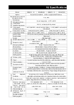
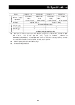
background image

55 

7. When the unit is not to be used for a long time 

or when disposing 

When the unit is not to be used for a long time or when disposing 


Caution


Warning


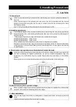
When  the  unit  is  not  going  to  be  used  for  a 
long time


  Turn the main unit power off and remove the 

power cord off the power supply. 

When disposing the unit


  Do not leave the unit where children may play 

around. 

  Remove  the handle to  prevent the door from 

locking before discarding the unit. 

  In general, dispose the unit as a bulky waste. 


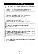
Notes about disposition 


Always pay attention to the preservation of the global environment.


We  highly  recommend  taking  the  unit  apart  as  far  as  possible  for  separation  or  recycling  to 

contribute to the preservation of the global environment. Major components and materials for the 

unit are as follows:


Names of major parts 

Major materials 

Major components of the main unit


Outer finish 

Steel sheet, melamine resin baking finish 

Internal bath 

Stainless steel 

Heat insulator 

Glass wool 

Door packing 

Silicone rubber (Fluororubber for model V) 

Handle 

Aluminum die-cast, epoxy melamine resin baking finish 

Nameplate 

Polyethylene

PET

resin film 

Major electric parts


Heater 

SUS321 stainless steel pipe heater 

Motor 

Composite  part  of  steel  plates,  cupper  wires,  and  resin  sheathed 

wires. 

Substrates 

Substrate

Epoxy resin, glass fiber 

Condensers, resistors, and transformers are installed on a substrate. 

Power  cord  and  other 

wiring materials, others 

Synthesized rubber sheath and resin sheathed wires. 


Summary of Contents for DKG610

Page 1: ...ons and Warranty before operating this unit to assure proper operation After reading these documents be sure to store them securely together with the Warranty at a handy place for future reference Warning Before operating the unit be sure to read carefully and fully understand important warnings in the operating instructions Yamato Scientific Co Ltd This paper has been printed on recycled paper ...

Page 2: ......

Page 3: ...ration 24 Creating a program 26 Program repeat operation 31 Program sheet 32 Useful functions calibration offset function 34 Useful function Lock function 35 Useful function External alarm output 36 Useful functions Output terminal 37 Option Overheat preventive unit 39 Option RS485 communication function 40 5 Handling Precautions 52 6 Maintenance procedures 54 Daily inspection maintenance 54 7 Whe...

Page 4: ...require hospitalization or outpatient visits for a long time Note 2 Minor injury means a wound or an electrical shock that does not require hospitalization or outpatient visits for a long time Note 3 Property damage means damage to facilities devices and buildings or other properties Meanings of pictograms This pictogram indicates a matter that encourages the user to adhere to warning caution incl...

Page 5: ... Hazard of explosion Caution General cautions Electrical shock Burning Caution for no liquid heating Caution for water leak For water only Poisonous material Prohibitions General bans Fire ban Do not disassemble Do not touch Compulsions General compulsions Connect ground wire Install levelly Pull out the power plug Regular inspection ...

Page 6: ...ords bundled When these are used bundled they might overheat causing a fire Take care not to damage electrical power cords Avoid tightly bend pull with a strong force or twist to prevent electrical power cords from damaging A fire or an electrical shock may result Never use an explosive or a flammable material with this unit Never use an explosive material a flammable material or a material contai...

Page 7: ...elow 2 Install the unit on a level surface Install the unit on a level surface If the whole bottom surface of the unit does not contact the surface evenly vibrations or noises may result This might cause unexpected troubles or malfunctions The unit weight DKG610 V 650 V Approx 110 DKG810 V 850 V Approx 155 When lifting the unit for transportation and installation carefully handle it by at least tw...

Page 8: ... splash Do not operate the unit at such a place that may subject to splash Liquid entering the inside may cause an accident a malfunction an electrical shock or a fire 6 Never operate the unit in an atmosphere containing flammable or explosive gas Never operate the unit in an atmosphere containing flammable or explosive gas Since the unit is not explosion proof an arc is discharged when switching ...

Page 9: ...fire Do not convert forcibly bend twist or pull the power cord Otherwise a fire or an electrical shock may result Do not place the power cord under a desk or a chair or sand between objects to avoid it from being damaged Otherwise a fire or an electrical shock may result Do not place the power cord close to a stove or other heat generating device Sheath of the cord may burn and result in a fire or...

Page 10: ...the load is evenly distributed Put specimens dispersed When shelf boards have been placed on all stages take care not to exceed the total withstand load Total withstand load DKG610 V DKG650 V 45Kg or less DKG810 V DKG850 V 75Kg or less Specimen 15kg Shelf board 13 Do not set too many specimens 14 Do not place an object on the bottom plate Too many specimens will prevent correct temperature control...

Page 11: ... the rectifier plate and never place the specimen directly 16 When using a wet material Drain off well the water of wet material before putting it in chamber in case to dry it Otherwise it may cause dew condensation or excessively high humidity and cause harm to electrical system Be careful that it may cause malfunction 17 About handling of the exhaust port manual damper The exhaust port is locate...

Page 12: ...sport the unit to the installation site Transporting the unit over a gap may give an excessive shock to the caster wheels and may damage them If such trouble is expected lift the unit and transport it over the gap 3 Lock the caster stoppers when the unit has been transported to the installation site They are locked 4 Connection of the power supply Make sure that the ELB is OFF before connecting th...

Page 13: ...al standard Optional part port Temp Output 4 20mA External com RS485 Shelf board ELB Operation panel Door Handle Temperature sensor access port Power cord Manual damper operation assembly Rating nameplate Serial nameplate Radiation port Exhaust damper access port and optional part auto damper connection port ...

Page 14: ... points Two front wheels have locks Temperature sensor access port Power cord Alarm output terminal standard Optional part port Temp Output 4 20mA External com RS485 Exhaust port Φ80mm Manual damper operation assembly 作部 Rating nameplate Serial nameplate Radiation port Exhaust damper access port and optional part auto damper connection port ...

Page 15: ...peration the target temperature may not be reached and adjust damper openness according to the specific conditions Average measured value for 5 points on the exhaust port looked from above Inside the bath Door Damper control assembly Circulation fan motor Heater Control sensor During regular operation Damper openness 0 Exhaust portφ80 Air supply port Exhaust flow at different damper openness envir...

Page 16: ...ature a temperature for calibration offset key lock and the program repeat function HEATER Lamp This lamp comes on while power is supplied to the heater ALARM Lamp Buzzer sounds and this lamp come on when an error occurs AUTO STOP Lamp This lamp flashes during quick auto stop timer setting and stays on during operation This lamp flashes during auto stop timer setting and stays on during operation ...

Page 17: ...o 3 See Creating a program on P 26 PAt Program pattern selection This is used to select a program pattern to use See Creating a program on P 26 End Time up This is displayed when Timer operation is finished See P 21 and 23 Sv 1 Program temperature setting This is used to set a temperature for each step of a program Displayed range is Sv 1 Sv 30 t 1 Program time setting This is used to set a time f...

Page 18: ...overheat preventive device See Setting the overheat preventive device on P 19 Lock Setting key lock Key locks settings to prevent their alterations See Useful functions Lock function on P 35 door Door open display This indication appears when the door is opened If you open the door during operation control heater and fan will be stopped and automatically recovers when you close the door For charac...

Page 19: ...set operation to automatically stop when setting Fixed Temp operation Press TIMER key to display AStP You can press ENTER key to set a set temperature Sv You can set an operation time tim by pressing ENTER key again Pressing RUN STOP key starts Auto Stop operation P 22 4 Auto Start operation This is used to automatically start several hours after turning power on Press TIMER key to display AStr Yo...

Page 20: ...ill stop and will not recover until the power switch is turned on again Manual recovery P 19 2 Calibration Offset function The Calibration Offset function compensates any differences that may occur between the target in bath temperature and the temperature on the controller sensor temperature You can compensate in plus or minus direction over the entire temperature range of the unit P 34 3 Overhea...

Page 21: ...1 30ステップ 1パターン PrG3 10ステップ 3パターン PrG2 15ステップ 2パターン プログラム モード選択 押して切り替え ENTER PAt プログラム パターン選択 ENTER RUN STOP 運転スタート RUN STOP 運転スタート FIXED TEMP TIMER ELB ON Fixed Temp operation Temp Setting 1 sec Operation Start Timer Operation Quick Auto Stop Auto Stop Fixed Temp Operation Status Time Setting Temp Setting Temp Setting 1 sec Timer Start Time Setting Time Setting 1 sec Operation Start Stop Automati...

Page 22: ...hen you turn power on the initial values will be displayed for about four seconds and the screen will change to the initial setting screen and each of indicators displays the current in bath temperature operation mode characters and overheat prevention set temperature MEASURED TEMP HEATER ENTER SET TEMP OVER TEMP RUN STOP SUB MENU TIMER FIXED TEMP PROGRAM PROTECTOR ALARM AUTO STOP AUTO START FIXED...

Page 23: ... FIXED TEMP PROGRAM MEASURED TEMP HEATER ENTER SET TEMP OVER TEMP RUN STOP SUB MENU TIMER FIXED TEMP PROGRAM PROTECTOR ALARM AUTO STOP AUTO START FIXED TEMP PROGRAM 2 Select an operation mode Press FIXED TEMP key to display Fix that means Fixed Temp operation on the set temperature indicator 3 Set a temperature Press FIXED TEMP key again Display the character Sv that means temperature setting on t...

Page 24: ...OVER TEMP RUN STOP SUB MENU TIMER FIXED TEMP PROGRAM PROTECTOR ALARM AUTO STOP AUTO START FIXED TEMP PROGRAM 2 Start timer operation When you have set a time you want press RUN STOP key for about one second Timer operation will start when the Fixed Temp operation lamp and the Auto Stop lamp are lit Timer starts when RUN STOP key is pressed 3 Stopping and ending Timer operation Operation will stop ...

Page 25: ...ator while the current set temperature and the Auto Stop lamp will flash on the set temperature indicator Press and keys to set a temperature you want Press ENTER key The character tim that means the timer is displayed on the measured temperature indicator and the current set time will flash on the set temperature indicator Use and keys to set a time you want About the timer function Maximum setta...

Page 26: ...en will switch to the initial setting screen When you want to correct a set temperature or a set time or check settings When you want to change the set temperature or the set time during operation press TIMER key without stopping operation set the temperature and the time for the Auto Stop operation using and keys and then press ENTER key for each setting But you need to set a time calculated by a...

Page 27: ...ured temperature indicator and the current set temperature and the Auto Start lamp will flash on the set temperature indicator Press and keys to set a temperature you want Press ENTER key The character tim that means a timer is displayed on the measured temperature indicator while the current set time flashes on the set temperature indicator and the Auto Start lamp flashes Use and keys to set a ti...

Page 28: ...the set time during operation press TIMER key without stopping operation set the temperature and the time for the Auto Start operation using and keys and then press ENTER key for each setting た But when you change the set time you need to set a time calculated by adding time period to add to the time already passed However you need to set a time calculated by adding time period to add to the time ...

Page 29: ...n sheets on P 32 33 of the operation manual check the number of steps temperature and time for each step beforehand Check the temperature increasing and decreasing capacity of the unit You need to set a time within the temperature increasing and decreasing capacity For example for a unit that is able to increase or decrease temperature by 50 for 10 minutes about 20 minutes will be necessary to inc...

Page 30: ...260 20 20 250 30 20 30 10 25 260 45 50 200 25 35 30 35 150 20 40 25 35 260 50 170 30 170 40 100 15 45 20 50 50 10 80 10 105 Creating a program Description here uses an example of a program pattern below Temp 1 Example program pattern 260 200 100 0 Step 1 2 3 4 5 6 7 Repeat function used No need to add the number of steps 8 Temp 100 100 150 150 200 200 50 50 Time 0 15 0 30 0 20 1 30 0 25 3 00 3 00 ...

Page 31: ...or any program mode you select from PrG1 PrG2 or PrG3 This section describes how to register a program when PrG3 is used as an example MEASURED TEMP HEATER ENTER SET TEMP OVER TEMP RUN STOP SUB MENU TIMER FIXED TEMP PROGRAM PROTECTOR ALARM AUTO STOP AUTO START FIXED TEMP PROGRAM 4 Registering a program Inputting a program Select PrG3 following the steps in the previous item 3 As per the programmin...

Page 32: ...s in the example program repeat a special procedures are necessary In such a case first set a time t 7 in the example for the step you want to perform repeat operation step 7 in the example and press SUB MENU key without pressing ENTER key Now you can enter the Repeat function setting mode For operation and registration input procedures for the Program Repeat function follow Program Repeat operati...

Page 33: ...es You can continuously change set time and change to the setting you want quickly by keeping and keys pressed Press and keys once at a time to fine adjust a time If you want to correct wrong settings or to check settings If you want to return to the previous step for example to correct a wrong program or to check settings again press FIXED TEMP key to return the Setting screen to the previous one...

Page 34: ...for a program pattern In the example the repeat function is input for the seventh step and the measured temperature indicator will display PS 7 In the set temperature indicator you can input a number of 1 7 of steps to return to 1 in the example using and key Then press SUB MENU key The measured temperature indicator displays the character Pc n that means a number of repetitions Input a number 2 i...

Page 35: ... Make duplicates as many as you need Register to PrG1 PrG2 PrG3 PAt1 PAt2 PAt3 Management Test name Date Prepared by Program pattern 30 29 28 27 26 25 24 23 22 21 20 19 18 17 16 15 14 13 12 11 10 9 8 7 6 5 4 3 2 1 260 250 200 150 100 50 Step ...

Page 36: ...me Date Prepared by Program inputs Set temperature Set time Time min Repeat function input Return to number Step 1 Step 2 Step 3 Step 4 Step 5 Step 6 Step 7 Step 8 Step 9 Step 10 Step 11 Step 12 Step 13 Step 14 Step 15 Step 16 Step 17 Step 18 Step 19 Step 20 Step 21 Step 22 Step 23 Step 24 Step 25 Step 26 Step 27 Step 28 Step 29 Step 30 ...

Page 37: ...e Sub menu key longer to finish setting You can set an offset compensation temperature to either or side up to 99 and 99 respectively Setting to the side will decrease the temperature on the measured temp indicator by the compensated temperature and the in bath temperature will increase by that amount accordingly Setting to the side will increase the temperature on the measured temp indicator by t...

Page 38: ... and cancel this function using SUB MENU key Press SUB MENU key select the character Lock that means setting lock with and keys and press ENTER key The set temperature indicator displays OFF Use key and change it to ON to lock the settings To cancel lock press SUB MENU key again select the character Lock that means setting lock with and keys and press ENTER key Select OFF with key and press ENTER ...

Page 39: ...terminal block Be sure to operate the unit at the rated capacity or below The setting will be ON relay contact close while outputting an alarm Connecting procedures Be sure to turn the ELB OFF before make connections Use the screws on the terminal block to secure connections Connection terminal When the optional auto damper is installed the standard external alarm output terminal will be eliminate...

Page 40: ...ure to connect a recorder having an input impedance of 600Ω or less to the temperature output terminal 4 Make any connection secure with the screws attached to the terminal block Connecting procedures Securely connect to the terminal to be used The alarm output and the time up output are ON relay contact closed at the time of outputting When temperature output is used use a shielded cable to preve...

Page 41: ...oad DC30V 3A resistance load Connection M4 screw terminal block Temperature Output current mA Converted voltage examples V 0 4 00 1 00 20 5 19 1 30 40 6 37 1 59 60 7 56 1 89 80 8 74 2 19 100 9 93 2 48 120 11 11 2 78 140 12 30 3 08 160 13 48 3 37 180 14 67 3 67 200 15 85 3 96 220 17 04 4 26 240 18 22 4 56 260 19 41 4 85 270 20 00 5 00 Reference value when voltage is input to the temperature recorde...

Page 42: ...ler or to the set temperature for the controller overheat preventive unit or higher Note that the overheat preventive unit is not available for the purpose of protecting specimens The temperature is set at 290 at the time of shipping If you want to operate the stand alone overheat preventive unit at a temperature you want first operate the unit with the temperature in the bath at that setting unti...

Page 43: ...ory external communication adaptor RS485 232C ODK18 you can make following connection PC unit is excluded Sample program can be viewed in our home page http www yamato net co jp support program index htm Connection communication cable PC CR5 controller RS232C 485 converter KS 485 Com cable 2 Com cable 1 AC adaptor COM1 COM2 Main unit Note 1 Configuration of the non standard accessory external comm...

Page 44: ...ct RO RW Note Settings indicated in are the initial settings of the Unit 3 Transmission control characters Symbol Name Code Description STX Start of text 02H Indicates the beginning of a text ETX End of text 03H Indicates the end of a text R Read 52H Command to read a request W Write 57H Command to write a request ACK Acknowledge Character 06H Transmission of acknowledgement of proper reception NA...

Page 45: ... 2 Message types Types of messages include the transmission request message from a host PC and the transmission reply message from the Unit All code excluding BCC including STX address request content identifier and ETX are expressed in ASCII codes 4 3 Configuration of the request message Transmission from a host PC to the Unit 4 3 1 Configuration of the read request message S T X R E T X B C C 4 ...

Page 46: ... S T X A C K E T X B C C 4 4 2 Reply message in response to the write request store request messages S T X A C K E T X B C C 4 4 3 Reply message when an error occurs S T X N A K E T X B C C Start code Address ACK code Identifier Numeric data End code BCC data Start code Address ACK code End code BCC data Start code Address NAK code BCC data End code Error type ...

Page 47: ...is read out from the Unit W When data is written into the Unit or stored in the Unit Identifier This is a classification symbol identifier for data to be read out or written and is expressed in a three digit ASCII code See 7 Identifier command list on page 49 Numeric data This is data to be read out or written all of which are expressed in a five digit number irrespective of their type Minus data ...

Page 48: ... the Unit when the message received with the Unit contains no error NAK This is a negative acknowledgement code and is returned embedded in a reply message from the Unit when the request message received with the Unit contains an error ERR type When a request message received with the Unit contains an error its description is embedded after NAK in the reply message from the Unit This is a communic...

Page 49: ...message Transmitted from a host computer S T X 0 2 R P V 1 E T X B C C Reply message Transmitted from the Unit Code Symbol data ASCII code note 2 Start code STX 02H Address 02 30H 32H Request Read R 52H Identifier note 1 PV1 50H 56H 31H Numeric data 00123 30H 30H 31H 32H 33H End code ETX 03H BCC data Request Reply 61H 02H Acknowledgement code ACK 06H Note 1 See 7 Identifier command list on page 49...

Page 50: ...ctly written by separately reading out the data Write request message Transmitted from a host PC Reply message Returned from the Unit S T X 0 3 A C K E T X B C C Code Symbol data ASCII code note2 Start code STX 02H Address 03 30H 33H Request Write W 57H Identifier note 1 SV1 53H 56H 31H Numeric data 00135 30H 30H 31H 33H 35H End code ETX 03H BCC data Request Reply 56H 04H Acknowledgement code ACK ...

Page 51: ...100Ω Terminating resistance Com cable 1 Main unit Up to 31 units can be connected Note1 Com cable 1 PC side connector for connecting IBM9 pin device RS 232C cable 1m KS 485 side connector Dsub25 pin male System Sacom CBL16 Note2 Com cables 2 3 These must be separately ordered Note3 Terminating resistance This must be separately ordered If the customer prepares this be sure to connect a fixed resis...

Page 52: ...select RPG R W 00001 ProgramNO 1select 00002 ProgramNO 2select 00003 ProgramNO 3select ProgramNO 2 Patternselect PT2 R W 00001 PatternNO 1select 00002 PatternNO 2select ProgramNO 3 Patternselect PT3 R W 00001 PatternNO 1select 00002 PatternNO 2select 00003 PatternNO 3select ProgramNO 1 Finalstepsetting E11 R W 00001 00030 Step1 step30 ProgramNO 2patternNO 1 Finalstepsetting E21 R W 00001 00015 Ste...

Page 53: ... 2nd digit Doorinputstatusoutput 3rd digit Mainoutput 4th digit Time upoutputoralarmoutput 5th digit Overheatprevention2output Outputstatus 0 outputOFF 1 outputON Errormonitor1 ER1 R 00000 1st digit Memoryerror 2nd digit Sensorerror 3rd digit ATerror 4th digit Heaterdisconnectionerrror 5th digit SSRshort circuiterror Errorstatus 0 Noerror 1 Error Errormonitor2 ER2 R 00000 1st digit Dooropen 2nd di...

Page 54: ...0H 31H 32H 33H 34H 35H 36H 37H 38H 39H Figures used 0 1 2 3 4 5 6 7 8 9 ASCII code 2DH 20H Figures used Minus SP Space ASCII code 41H 42H 43H 44H 45H 46H 47H 48H 49H 4AH Char used A B C D E F G H I J ASCII code 4BH 4CH 4DH 4EH 4FH 50H 51H 52H 53H 54H Char used K L M N O P Q R S T ASCII code 55H 56H 57H 58H 59H 5AH 20H Char used U V W X Y Z SP Space ...

Page 55: ... is heard When thunder is heard immediately turn the power of the unit off and then shut the power supply off Leaving the unit in such condition may cause a malfunction or a fire by lightening 3 When opening closing door When opening or closing a door do not put your hands or face close to its moving range space The door may hit your hand or face and cause a personal injury 4 Do not operate the un...

Page 56: ...too many specimens may prevent proper temperature control To assure temperature control precision put specimens taking care so that at least 30 or more space are assured on shelf boards 9 Do not place any specimens on the bottom of inside the bath Using the unit with specimens placed directly on the bottom inside the bath may prevent the unit from exercising its highest performance as well as in b...

Page 57: ...ff any dirt with a tightly wrung soft cloth Never try to clean the unit with benzene thinner or scouring powder or rub with a scrubbing brush Deformation degradation or discoloration may result Every month Inspect the functions of the ELB Test shall be performed with the power cord connected and power is being supplied to the unit First turn the ELB to ON Then press the test button on the device w...

Page 58: ...sible for separation or recycling to contribute to the preservation of the global environment Major components and materials for the unit are as follows Names of major parts Major materials Major components of the main unit Outer finish Steel sheet melamine resin baking finish Internal bath Stainless steel Heat insulator Glass wool Door packing Silicone rubber Fluororubber for model V Handle Alumi...

Page 59: ...sconnection or other errors in the temperature sensor Contact our service department Detection of SSR short circuit Alarm lamp on indication SSR short circuit Contact our service department Detection of heater disconnection Alarm lamp on indication Heater disconnection Current detecting element disconnection or error Temperature fuse blown out Contact our service department Memory error Alarm lamp...

Page 60: ...g the specification is not used when connecting the exhaust duct Check the procedures for connecting the exhaust duct in 17 About handling of the exhaust port manual damper on P 8 Temperature fluctuates during operation If the set temperature is appropriate If the power supply voltage has declined IF fluctuation of the environmental temperature has become large If load for inside the bath is large...

Page 61: ...ate of purchase and other information and fax it to our customer center 03 3231 6523 then store it securely Warranty period is one full year from the date of purchase Repair service for free is available according to the conditions written on the warranty card For repairs after the warranty period consult your dealer or one of our sales offices Paid repair service is available on your request when...

Page 62: ...ystem Digital setting system with dedicated menu keys and keys Display system Measured temp display 4 digit green LED digital display Set temp display 4 digit red LED digital display Timer 1 min 99 hrs 59 min and 100 hrs 999 5 hrs with Timer Wait function Timer resolution 1 min or 10 min Operation function Fixed Temp operation Program operation Quick Auto Stop operation Auto Stop operation Auto St...

Page 63: ... boards Punched stainless steel 2 4 Shelf pegs 4 8 Operation manual warranty card 1 Performance data has been measured at room temperature of 23 5 humidity of 65 RH 5 and no load with the power supply of AC200V AC230V for DKG650 V DKG850 V Temperature rise time is for when the exhaust port is closed while the temperature fall time is for when the exhaust port is opened 2 Heater capacity is for the...

Page 64: ...Leakage Breaker PLB VS4PG controller T1 T2 T4 Terminal block PIO Display substrate H1 H2 Heater K1 Control sensor X1 X3 Relay K2 Overheat preventive sensor FM1 Circulation fan motor FM2 Cooling fan CT Current sensor SSR1 No contact relay F1 Temperature fuse DS Door switch TF1 Transformer ...

Page 65: ...ectric Leakage Breaker PLB VS4PG controller T1 T4 Terminal block PIO Display substrate H1 H2 Heater K1 Control sensor X1 X3 Relay K2 Overheat preventive sensor FM1 FM2 Circulation fan motor TF1 Transformer CT Current sensor SSR1 No contact relay F1 Temperature fuse DS Door switch ...

Page 66: ... Socket AP3822K Panasonic 2050081004 Door packing DNE65 40791 Silicon Yamato LT00033164 Door packing DNE65V 40001 Viton Yamato LT00033165 Handle box DNE60 40080 Yamato DNE6040080 Axis DNE60 40290 Yamato DNE6040290 Hook A DN93S 40000 Yamato DN931 Hook B DN93S 40010 Yamato DN932 Spring DNE60 40710 Yamato DNE6040710 Handle DTS82 30820 Yamato DTS8230820 Push DTS82 30830 Yamato DTS8230830 Stopper DTS82...

Page 67: ...30061 K2 Sensor 08L 0130 NT Nihondensoku LT00030147 Power cord T3 3e 4 5m Yamato 2130056006 ELB Electric leakage breaker BJS3032S Panasonic LT00029545 T3 Terminal block MKH 250ABC 4P Terminal LT00035672 Sirocco fan S2 158053L 8G CCW Rokugo DN002 Sirocco fan S2 158053R 8G CW Rokugo DN169 DKG850 V replacement parts Symbol Part name Specifications Manufacturer Code FM2 Motor IC 8434 YAMB 1 200V30WCW ...

Page 68: ...te and other perchlorates Potassium Peroxide Sodium Peroxide Barium Peroxide and other inorganic peroxides Potassium Nitrate Sodium Nitrate Ammonium Nitrate and other nitrates Sodium Chlorite and other chlorites Calcium Hypochlorite and other hypochlorites Flammable Substances Ethyl Ether Gasoline Acetaldehyde Propylene Chloride Carbon Disulfide and other substances with ignition point at a degree...

Page 69: ...ation P 16 3 Operation start Auto stop Perform Auto Stop operation Input 2 minutes to the auto stop mechanism and check for the proper operation 4 Operating Procedures Auto Stop operation P 16 4 Operation start Auto start Perform Auto Start operation Input 2 minutes to the auto start mechanism and check for the proper operation 4 Operating Procedures Auto Start operation P 16 5 Program operation P...

Page 70: ...riptions in this operating instruction are subject to change without notice We will replace a manual with a missing page or paging disorder Instruction Manual Rapid Heating Cooling oven DKG610 V DKG650 V DKG810 V DKG850 V Third edition June 15 2012 Revised on November 17 2017 103 0022 Muromachi Higashi Mitsui Building COREDO Muromachi 2 2 1 Muromachi Nihonbashi Chuo city Tokyo General customer ser...

Reviews: