8
Description and Function of Each Part
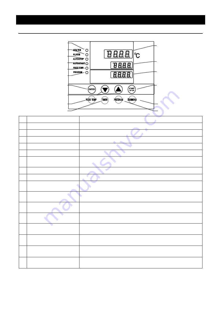
Control Panel
①
START/STOP Key
:
Starts/stops the operation.
②
▲▼
Key
:
Uses for rising UP/lowering DOWN the setting value.
③
ENTER Key
:
Settles the inputted value.
④
FIXED TEMP Key
:
Chooses the fixed temperature operation.
⑤
TIMER Key
:
Chooses the timer operation (Quick Auto Stop/Auto Stop/ Auto Start).
⑥
PROGRAM Key
:
Chooses the program operation or program creation mode.
⑦
SUBMENU Key
:
Uses for setting the overheating prevention temperature, calibration
offset temperature, key lock function, or program repeat function.
⑧
HEATER Lamp
:
Lights while the heater works.
⑨
ALARM Lamp
:
Lights up when an error occurs. (Buzzer sounds simultaneously.)
⑩
AUTO STOP Lamp
:
Blinks while setting quick auto stop timer or auto stop timer.
Lights while quick auto stop timer or auto stop timer is running.
⑪
AUTO START Lamp
:
Blinks while setting auto start timer.
Lights while auto start timer is running.
⑫
FIXED TEMP Lamp
:
Blinks while setting fixed temperature operation.
Lights while fixed temperature operation is running.
⑬
PROGRAM Lamp
:
Blinks while setting program operation.
Lights while program operation is running.
⑭
Measurement Temperature
Display
:
Displays the measured temperature, setting character, alarm
information.
⑮
Setting Temperature
Display
:
Displays the setting temperature, setting value for timer mode,
remaining time.
⑯
Overheating Prevention
Temperature Display
:
Displays the setting temperature for overheating prevention device.
⑰
Power Switch
:
(circuit breaker)
Turns ON/OFF the main power.
⑧
⑨
⑩
⑪
⑫
⑬
③
②
④
⑤
⑦
⑥
①
⑯
⑮
⑭


