background image


ULTRA LOW FREEZER 

ULF SERIES 

MODEL 

ULF701C / ULF901C 


INSTRUCTION MANUAL 

- FIRST EDITION – 


  Thank you for purchasing ULF Series Ultra Low Freezer of Yamato 

Scientific 


  To use this unit properly, read this "Instruction Manual" thoroughly 

before using this unit. Keep this instruction manual around this unit 

for referring at any time. 


WARNING: Carefully read and thoroughly understand the important 

warning items described in this manual before using this unit. 


Yamato Scientific America Inc. 

Santa Clara, CA 


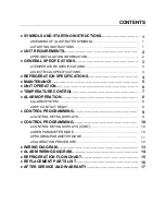
Summary of Contents for ULF701C

Page 1: ...ato Scientific To use this unit properly read this Instruction Manual thoroughly before using this unit Keep this instruction manual around this unit for referring at any time WARNING Carefully read and thoroughly understand the important warning items described in this manual before using this unit Yamato Scientific America Inc Santa Clara CA ...

Page 2: ... REFRIGERATION SPECIFICATIONS 4 MAINTENANCE 5 UNIT OPERATION 6 TEMPERATURE CONTROL 7 ALARM OPERATION 8 ALARM SYSTEM 8 DRY CONTACT RELAY 8 CONTROL PROGRAMMING 9 CONTROL KEYS DISPLAYS 9 CONTROL PROGRAMMING 10 CONTROL KEYS DISPLAYS CONT 10 USER PARAMETER MODE 10 PROGRAM PARAMETER MODE 11 CALIBRATION PROCEDURE 12 WIRING DIAGRAM 13 ALARM WIRING DIAGRAM 14 REFRIGERATION FLOW CHART 15 REPLACEMENT PARTS L...

Page 3: ...EXCLAMATION POINT CAUTION REFER TO ACCOMPANYING DOCUMENTS 1 Move the freezer to an indoor location and plug the freezer into an appropriate outlet with an adequate power supply Consult your maintenance department for additional information on the proper electrical configuration for this unit 2 Once plugged in the compressor s will start to operate and pull down to the setpoint on the temperature c...

Page 4: ...lly present on the mains supply overvoltage category II Pollution degree 1 WARNING THIS FREEZER IS PROVIDED WITH AN INPUT CIRCUIT PROTECTIVE DEVICE WHICH SHALL BE MAINTAINED AND SERVICED BY QUALIFIED PERSONNEL ONLY CAUTION FUSES OR BREAKERS USED INSIDE PROTECTIVE DEVICE 15A OR 20A 250V TIME DELAY CAUTION UNPLUG FREEZER BEFORE ANY TECHNICAL SERVICE IS PERFORMED ON THE UNIT WARNING DO NOT POSITION E...

Page 5: ... a Dedicated Electrical Line MODEL VOLTAGE AMPERAGE PLUG ULF701C ULF901C 208 220 230 VOLTS 60 HERTZ 1 PHASE 20 AMP DEDICATED LINE NEMA 6 20 WARNING ONLY PLUG THIS UNIT INTO THE PROPER OUTLET DO NOT ATTEMPT TO MODIFY PLUG IN ANY WAY IMPROPER USE OF THE ELECTRICAL PLUG WILL VOID WARRANTY 3 GENERAL SPECIFICATIONS TEMPERATURE SPECIFICATIONS ELECTRICAL SPECIFICATIONS ...

Page 6: ... STAGE REFRIGERANT LOW STAGE REFRIGERANT ULF701C 21 1 HP TECUMSEH R404A 23 oz R170 30 to 20 psi R508B 130 psi ULF901C 27 1 HP TECUMSEH R404A 23 oz R170 30 to 20 psi R508B 130 psi 4 REFRIGERATION SPECIFICATIONS REFRIGERATION SPECIFICATIONS ...

Page 7: ... in the freezer and store it in a back up freezer or elsewhere 2 Unplug the freezer and open the freezer front door lid 3 Use a cloth to protect the control from dripping water 4 Air out the freezer for at least 12 hours allowing the unit to reach room temperature 5 Take a rag and wipe up all the excess water in the unit melted frost 6 Plug the unit in and set your temperature to the desired setpo...

Page 8: ...system cycles off on high pressure control WARNING ALWAYS LEAVE THE REFRIGERATION SWITCH IN ON POSITION AS THIS WILL AUTOMATICALLY ACTIVATE THE AUTOMATIC STARTING SYSTEM CAUTION COVER SCREEN ON BACK OF FREEZER MAY ONLY BE REMOVED BY AUTHORIZED PERSONNEL ONLY FOR CONNECTIONS TO THE EXTERNAL ALARM COVER SCREEN MUST BE REPLACED BEFORE PUTTING FREEZER INTO SERVICE FAILURE TO REINSTALL COVER COULD RESU...

Page 9: ...ATURE SETPOINT The temperature set point can be changed by simply pressing the up arrow to raise or the down arrow to lower the temperature set point WARNING CHANGING THE CONTROL PARAMETERS OUTSIDE OF THE MANUFACTURE RECOMMENDED RANGE COULD SHORTEN THE LIFE SPAN OF YOUR EQUIPMENT OR CAUSE ISSUES RESULTING IN MECHANICAL FAILURE WARNING USE ONLY THE UP AND DOWN KEYS WHEN MAKING CHANGES ON THIS CONTR...

Page 10: ...e batteries should be changed approximately every three years with lead acid rechargeable 1 2 Ah min model PS 640F1 or equivalent WARNING ALARM SYSTEM SHOULD BE TESTED EVERY 30 DAYS The dry contact relay is a terminal strip located on the back of the freezer RATING OF THIS CONNECTION 2A 125 VAC 2A 30 VDC RED NORMALLY CLOSED WHITE COMMON BLUE NORMALLY OPEN WARNING IF IT IS NECESSARY TO REMOVE METAL...

Page 11: ...or 2 seconds and release to silence audible alarm under normal power or on battery power While unit is in an alarm condition the external alarm relay contacts will remain energized until the alarm condition no longer exists Press and hold to display chamber temperature while the controller is on battery power Chamber temperature will be displayed until key is released Alarm contact will remain ene...

Page 12: ...utton is pressed to display the process value Note When operating on battery power the battery status LED labeled BAT on the front panel will be lit To enter the USER parameter mode hold the scroll key for 2 seconds and release To enter the user parameter mode hold the Scroll Button for 2 seconds and release To make changes in the user parameter mode press the up or down arrows To exit the user pa...

Page 13: ...tial 22 12 X AHY 3 1 Alarm Hysteresis 1 8 1 0 X OHY 3 1 Output Hysteresis 3 6 2 0 X RB 1 Alarm Delay in Minutes 30 X DoR 4 Door Alarm X SP 2 Setpoint X IN2 4 N A N A TO EXIT TAP SCROLL KEY REPEATEDLY UNTIL TEMPERATURE SETPOINT SCREEN APPEARS 1 This parameter has been turned on by pressing either arrow key and then make your changes in user mode THE VALUES TO BE CHANGED ARE DISPLAYED IN USER MODE O...

Page 14: ...e value to ON PARAMETERS DESCRIPTION F C ON OFF SPL 3 Lower Setpoint SPH 3 Upper Setpoint Al 2 Alarm INV 1 Temperature Scale SHF 1 Calibration X Hold SCROLL KEY for 2 seconds and release SHF should appear in the top display and the current calibration value should appear in the bottom display The value can now be changed with UP or DOWN arrow keys Once finished press and release the SCROLL KEY to ...

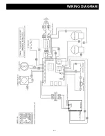
Page 15: ...13 WIRING DIAGRAM ...

Page 16: ...14 ALARM WIRING DIAGRAM ...

Page 17: ...15 REFRIGERATION FLOW CHART ...

Page 18: ... Specify Voltage 231 VOLTAGE REFRIGERATION HIGH STAGE PARTS PART Air Cooled Condenser No 3CZ0602B 254 Drier No C 053 S 256H Capillary Tube HS 17 HS 20 Oil Separator Temprite Series 900 If Applicable 900 REFRIGERATION LOW STAGE PARTS PART Pressure Control No 20PS01 0039 259 Receiver Condenser RCN LS Drier No CO 52S S 256L Capillary Tube LS 28 LS 31 Oil Separator Temprite Series 900 If Applicable 90...

Page 19: ...ditions This warranty shall have force and effect only if all items are used with proper circuits voltages and frequencies and the operation thereof is in accordance with instructions furnished by the manufacturer This warranty shall not extend to such parts as refrigerants finishes belts and dryers This warranty shall not extend to ordinary wear and tear or ordinary refrigeration service and refr...

Page 20: ...s are subject to a 25 restocking fee Shipping and handling cost are non refundable All retrofitted customized and special order item sales are final and non returnable In Case of Request for Repair If the failure occurs stop the operation turn OFF the power switch and unplug the power plug Please contact the sales agency that this unit was purchased or Yamato Scientific s sales office Check follow...

Reviews: