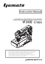
background image

Instruction Manual

This instruction manual includes adjustments differed  from  VF2400.

Before using  your  machine mentioned above, please read both of  

the instruction manuals and understand  the contents  well. 
After  reading  the instruction manual, please keep it  in a location 
where it  is easily  accessible  to  the operator.

HIGH SPEED FLAT BED INTERLOCK STITCH MACHINE

VF2400 class

Summary of Contents for VF2400 class

Page 1: ...efore using your machine mentioned above please read both of the instruction manuals and understand the contents well After reading the instruction manual please keep it in a location where it is easily accessible to the operator HIGH SPEED FLAT BED INTERLOCK STITCH MACHINE VF2400 class ...

Page 2: ... Lubrication 13 4 1 Lubricating oil 13 4 2 Lubricating 13 4 3 Changing oil 14 4 4 Checking and replacing oil fileter 14 5 Proper operation 15 5 1 Needle system 15 5 2 Installing needles 15 5 3 Threading 16 5 4 Adjusting thread tension 17 5 5 Pressure of presser foot 17 5 6 Adjusting position of presser foot 17 5 7 Adjusting differential feed dog 18 5 8 Adjusting stitch length 19 5 9 HR device and ...

Page 3: ...y for technicians but it is advisable that also operators read the instructions with mark to use the machine properly The numbers in lower left corners of figures are figure numbers We use them in texts as needed for your reference 6 Adjustments 24 6 1 Needle thread tension 24 6 2 Top cover thread tension 25 6 3 Looper thread tension 26 6 4 Removing presser foot and presser foot lift 27 6 5 Looper...

Page 4: ...mato SF oil as specified 3 Never put your hand under the needle or near the moving parts of the machine when turning on power supply switch 1 To ensure safe use Always observe the following instructions to en sure the safe use of the industrial sewing ma chines and devices 1 1 Application and purpose The sewing machine is designed to improve pro ductivity in the sewing industry and must not be use...

Page 5: ...o you and others Caution indicates hazardous situations which if not heeded may result in minor or moderate injury to you and others or may result in ma chine damage NOTE is used to emphasize essential informa tion 4 When operating a new sewing machine make sure the rotating direction of pulley agrees with the rotating direction mark 2 5 During operation 1 Be sure to operate the sewing machine wit...

Page 6: ...removal of the safeguards and works except for sewing per formance while the power supply switch is on are prohibited For details see the next page High voltage applies in the control box This label indicates that electric shock may be caused This label is affixed on the safeguards Considering the operation it is not affixed on the finger guard and eye guard Be sure to operate with the finger guar...

Page 7: ...iv Safety instructions Rotating direction symbol ...

Page 8: ...ht window Needle bar cover Presser spring regulator Needle thread take up guard Feed regulating pushbutton Side cover Differential feed graduation Finger guard Presser foot Eye guard Front cover Supporting plate for looper thread take up Oil sight gauge Looper thread take up cover Thread tension spring cap ...

Page 9: ...ed type 2 Installation 2 1 1 Table cutting diagram Fig 2 1 Standard Table dimensions 1200 595 40 Operator center of pulley Refer to the instruction manual of the motor for dimensions A B C and D Section Y Y 1 2 Section X X 1 2 ...

Page 10: ...tallation With UT device Fig 2 2 Refer to the instruction manual of the motor for dimensions A B C and D Section Y Y Section X X Operator Table dimensions 1200 595 40 center of pulley 3 φ 9 5 installing hole of motor ...

Page 11: ...g board and cover the screws with the rubber cushions Fix the the sup porting board to the machine table and install a machine securely on the rubber cushions The number of spacers VF2400 class s e w i n g machine machine table Fig 2 4 4 Thickness of table The number of spacers 40 3 pcs 4 12 pcs 45 2 pcs 4 8 pcs 50 1 pc 4 4 pcs Table 1 ...

Page 12: ...t magnet magnet Table Supporting board Note 125 is reference dimension which differ by kindes of the motor 155 in the above figure is the distance to the bottom of the supporting board so it must be set to the dimension where there will be no interference between the motor control panel and the bottom and back end of the supporting board Note Position of the rear end of supporting board Note 125 M...

Page 13: ...6 VF2400 2 Installation Fig 2 6 Fig 2 7 Supporting board Auxiliary table thickness 20 thickness 35 ...

Page 14: ... referring to Figs 2 8 and 2 9 Set the screws in the supporting board and cover the screws with the rubber cushions Fix the the sup porting board to the machine table and install a machine securely on the rubber cushions 2 2 2 Installation Fig 2 9 machine table ...

Page 15: ...he sewing machine will be over maximum and it can cause the damage to the machine Servomotor Use a servomotor with 500 W or more Calculate the outside diameter of a motor pulley from the formula as below Or see Table 3 to select a proper motor pulley Outside diameter Usual sewing speed of motor pulley Servomoter speed 58 5 mm Table 3 Outside diameter of pulley Sewing speed of machine sti min Belt ...

Page 16: ...lley and then on the motor pulley while rotating the machine pul ley 2 Adjust the belt tension so that the belt has a slack of 10 20 mm when its center is pushed with 10 N 3 Lock the motor with the adjusting bar Before hanging belt ALWAYS turn the power switch OFF and check that the machine has already stopped Set the belt cover Fig 2 12 ...

Page 17: ...push it to the left 2 Fix the thread guide plate with the screws se curely 2 Installation 2 6 Eye guard and finger guard To ensure safe use always install the eye guard and the finger guard on the prescribed position when operating Fig 2 13 2 7 Thread guide plate Fig 2 14 ...

Page 18: ...4 Fig 2 17 1 Set the tape stand Fig 2 15 2 Fix the tape stand on the machine table with the wood screws Fig 2 16 3 Adjust the direction of the tape guide bar to feed a tape into the folder smoothly Set the tape holder on the screw of the top cover and the screw of the head cover with the screws respectively ...

Page 19: ...g service life in good condition The rotating directions of the machine pulley and the handwheel are clockwise as shown in the figure Fig 3 1 If rotated in reverse direction oil cannot be supplied properly It can cause the damage to the machine Table 4 Model Max speed sti min Usual speed sti min VF2400 2500 with spreader 6500 6000 VF2403 2503 with spreader 6000 5500 VF2404 2504 with spreader 5000 ...

Page 20: ...ight window while running a machine If oil does not splash from the nozzle see 4 4 Checking and replacing oil filter on page 14 Before lubricating ALWAYS turn the power switch OFF and check that the machine has already stopped Never add additives to the oil If added it can cause the deterioration of the oil and the damage to the machine Too much or insufficient oil can cause oil leakage and machin...

Page 21: ...oving screw oil is drained If the oil filter is clogged with dust lubrication can not be done properly Remove the oil filter cap and the oil filter to check them every six months If clogged or cracked clean or replace the oil filter If oil is splashed from the nozzle insufficiently or in cludes many bubbles though the oil is sufficiently kept check or replace the oil filter Fig 4 4 6 Reset the scr...

Page 22: ... of tweezers 3 Insert a new needle into the needle clamp as far as it will go with facing its scarf to the right back Figs 5 2 and 5 3 4 Tighten the screws with a screwdriver Table 5 Fig 5 1 Fig 5 3 Fig 5 2 Tighten the screws with a tightening torque of 0 6 N m Before installing ALWAYS turn the power switch OFF and check that the machine has already stopped NO OK NO Japanese standard 9 10 11 12 13...

Page 23: ...eaded rethread after knotting preset threads When not threaded thread correctly as shown in Fig 5 4 Incorrect threading can cause skip stitch thread breakage or uneven seam A B C Needle thread D Top cover thread E Looper thread Fig 5 4 shows threading for 3 needle machine Two needle threads are used for 2 needle machine Looper thread Pull the thread until the knot is out Then cut off the knot Fig ...

Page 24: ...the pressure To increase the pressure turn it clockwise To decrease the pressure turn it counterclockwise Keep the pressure as low as possible for stable sewing per formance 5 6 Adjusting position of presser foot Adjust left and right position of the needle holes of the presser foot Loosen the screw Move the front of the presser foot right or left so that the needles drop in the centers of the nee...

Page 25: ...ifferential feed is 1 2 2 Reverse differential feed stretching To obtain reverse differential feed lower the differen tial lever left below the graduation When it is set at S the ratio of main feed to differ ential feed is 1 0 7 3 Adjustment of differential feed during operation To adjust differential feed during operation connect the chain to the differential lever left Fix Stop 2pcs at the desir...

Page 26: ...n of the pul ley with the mark on the machine 3 Release the pushbutton To decrease stitch length turn the pulley in the direction S To increase stitch length turn the pulley in the direction L Stitch length can be adjustable from 1 4 to 3 6 mm Table 7 shows the number of stitches per inch 25 4 mm and 30 mm converted to the stitch length Check that push button is released completely and the pulley ...

Page 27: ...high speed or using synthetic thread and or synthetic fabric Use dimethyl silicon oil 1 When not using SP or HR device remove the felt or If attached It may occur irregular condition during sewing 2 If silicone oil is attached to the parts other than SP and HR devices it can cause the machine trouble Be sure to wipe it away Note Open the seal plug of HR container and the lid of SP container to che...

Page 28: ...nd VF2504 Fig 5 15 Fig 5 16 5 11 1 Setting elastic tape Set the tape role on the tape stand Fig 5 15 Pull a tape forward through the folder and set it under the presser foot Unmatched folder width with tape width cannot be folded properly Set an elastic tape correctly Fig 5 16 Pushing the roller lever can make a clearance between the rollers Set an elastic tape under the presser foot and pull it f...

Page 29: ...wise and move the pointer in the direction L To decrease feeding amount turn the adjusting screw counterclockwise and move the pointer in the di rection S Tighten the nut securely after adjusting If required feeding amount cannot be obtained by above adjusting with the adjusting screw loosen the screw and adjust it as below To decrease feeding amount turn the adjusting screw clockwise To increase ...

Page 30: ...leaning the machine Hemming guide left 1 Loosen the screw of the hemming guide left 2 Adjust right and left position to align the fabric end to the left needle 3 Tighten the screw securely Hemming guide right 1 Loosen the screws of the hemming guide right 2 Adjust right and left position to align the fabric end with hemming width 3 Tighten the screws securely Before operating ALWAYS turn the power...

Page 31: ...he screw securely To tighten the needle thread tension move the needle thread take up in the direction T To loosen the needle thread tension move the needle thread take up in the direction L To tighten the needle thread tension move the needle thread eyelet in the direction T To loosen the needle thread tension move the nee dle thread eyelet in the direction L T L 8 6 Adjustments Before adjusting ...

Page 32: ...t the lowest point Loosen the screw to adjust the height and right and left position of the needle thread guide 6 2 Top cover thread tension Fig 6 5 Loosen the screw and move the top cover thread eyelet right to adjust it To decrease take up amount move the top cover thread eyelet right in the direction T To increase take up amount move the top cover thread eylet right in the direction L When usin...

Page 33: ...se take up amount move the thread take up eyelets frontward To decrease take up amount move the thread take up eyelets forward Too much take up of the looper thread can cause skip stitch For stretchable thread Move the thread take up eyelets frontward fully and never thread it through the supplementary tension disc Fig 6 8 Fig 6 9 thread 1 2 Fig 6 8 shows the looper thread take up seen from the ne...

Page 34: ...er foot to 7 0 mm with spreader needle distance 5 6 mm on VF2500 2 Tighten the screws securely 3 With keeping that make the clearance between the end of the presser bar bushing and the top of the collar to 0 2 mm 4 Tighten the screws securely After adjusting push down the lifter lever fully to check the height of the presser foot Presser foot lift depends on the machine model or needle distance Se...

Page 35: ...95220 makes it possible to adjust the distance easily The gauge is an special order part Place an order from our agents or directly from us Table 8 The distance between the center of the needle bar and the looper tip is 6 0 mm even if the needle distance changes 6 5 2 Distance between looper and needle Fig 6 12 Fig 6 13 Fig 6 14 6 0 Insert the looper into the looper holder fully and tighten the sc...

Page 36: ...serted fully into the needle holes of the needle clamp and fixed securely Looper should be inserted fully into the looper holder and fixed securely Adjusting 1 Install the needle to the left hole in the needle clamp 2 Check the looper is inserted into the looper holder fully 3 Turn the handwheel until the looper tip meets the cen ter of the left needle 4 Loosen the screw of the needle bar bracket ...

Page 37: ...n the looper tip meets the right needle they touch slightly by 0 2 mm Make the clearance between them to 0 0 05 mm to push the needle guard rear to the right needle Loosen the screw of the looper holder to adjust it 2 needle When the looper tip meets the left needle make the clearance between them to 0 2 0 3 mm When the looper tip meets the right needle they touch slightly by 0 2 mm Make the clear...

Page 38: ... rear position When the looper tip meets the center of the right needle make the clearance between them to 0 0 05 mm to push the needle guard rear to the right needle Make the clearance between the left needle and the needle guard rear to 0 05 0 1 mm Loosen the screws to adjust them Make the clearance between each needle and the needle guard front to 0 0 3 mm respectively when the looper tip comes...

Page 39: ...mm Adjust the height of the spreader so that the top cover thread passes behind the right needle and be caught by the left needle within adjustable range based on the nee dle distance Make the clearance between the left needle and the hook a to 0 5 0 8 mm when the spreader moves from the right to the left Make the clearance between the center of the left needle and the hook a to 4 5 5 5 mm when th...

Page 40: ...e eye of the top cover thread eyelet along the ex tending line from the slot of the top cover thread guide Tighten the screw securely Adjust the spreader the top cover thread guide and the top cover thread eyelet properly depending on the thread to be used Make the clearance between the bottom of the top cover thread guide and the top of the spreader to 0 5 mm Tighten the screws securely where the...

Page 41: ... position Loosen the screws to set the folder to align the left end of a tape with the left needle depending on its specifica tions Up and down position Loosen the screw to set the fabric slide plate 1 3 up from the bottom of the folder exit Set right and left position of the fabric slide plate to align its end with the right end of a fabric Loosen the screw to adjust it fabric left needle tape Fi...

Page 42: ...the tape guide to guide a tape smoothly depending on a tape width 3 After positioning the tape guide bar long loosen the screw to position the tape guide stopper It prevents the needle bar from touching the tape guide c set and makes the position of the tape guide bar long Set the presser foot tape guide depending on the needle distance and a part to be sewn on a tape Loosen the screw to adjust it...

Page 43: ...eeds an elastic tape correctly An automatic elastic feeder AEF 31 can feed an elas tic tape smoothly and constant sewing finish can be ob tained REFERENCE Replacement and repair Improper installation of the metering device can cause im proper feeding of an elastic tape skip stitch needle break age bad sewing performance and others Carefully install the device as following points Lubrication Remove...

Page 44: ...AS of Shumetz or Organ 65 90 Needle Distance 3 needle 4 8 5 6 6 0 6 4 mm 2 nnedle 3 2 4 0 4 8 6 4 mm 2 nnedle 4 0 4 8 6 4 mm 3 needle 4 8 5 6 6 4 mm 2 nnedle 3 2 4 0 4 8 6 4 mm Needle Stroke 31 mm Presser Foot Lift 6 0 mm needle distance 6 4 mm 8 0 mm 3 2 mm with spreader 7 0 mm without spreader 8 0 mm without spreader 8 0 mm 5 0 mm needle distance 6 4 mm 7 0 mm 3 2 mm without spreader 7 0 mm Feed...

Page 45: ...r 30 mm Needle system UY X 128GAS of Shumetz or Organ 65 90 Needle Distance 3 needle 5 6 mm 2 nnedle 3 2 4 0 4 8 6 4 mm 3 needle 5 6 6 4 mm Needle Stroke 31 mm Presser Foot Lift 5 0 mm needle distance 6 4 mm 7 0 mm 3 2 mm without spreader 7 0 mm with spreader 8 0 mm Feed Regulation Push button system Differential Ratio 1 0 7 1 2 Differential Feed Regulation External lever even during operation Lub...

Page 46: ...MA KIT A KU OSAK A JAP AN T E L 81 6 636 4 5621 F A X 81 6 6365 7185 530 0047 大 阪 市 北 区 西 天 満 4 丁 目 4 番 1 2 号 TEL 06 6364 5621 代 FAX 06 6365 7185 Printed in Japan 2010 2 3H U P N 9720028 I No 7 Edited in 2010 2 VF2400 ...

Reviews: