A05G069A
8
6.
OPERATIONS
⚫
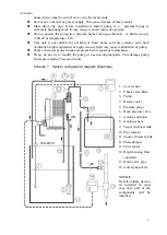
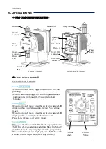
PUMP COMPONENTS DESCRIPTION
:
Hose cap Panel cover Purge valve
Outlet
connector
Operation
panel
Pump Stroke knob
head
Display
Pump
Inlet Signal I/O body
connector connector
Hose
cap Power/level
connector
Rotatable
base
FRONT SIGHT SEMI-BACK SIGHT
⚫
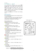
PANEL DESCRIPTION
:
SWITCHES AND KNOB
:
Switch -RUN/STOP
When not in batch mode, toggle this switch to stop/run
pumping.
When in batch mod, toggle this switch to pause/resume
pumping, pressing longer than 5 seconds to abort
batching.
Switch -DISP.
When not in batch mode, press this switch to change LED
display within 3 unit3(Pause/min, ml/min, % of setting
range)
When not in batch mode, press this switch to change LED
display within in 4 units(Countdown in seconds,
Pause/min, ml/min, % of setting range)
Switch -MODE
Press over than 5 seconds to blink LED display then press
MODE to change operation mode from Mode1 to Mode9
(number of modes may very depend on the pump model)
When selected mode was displayed, press MODE over 5
seconds to enter target mode.(LED stop blinking)
Current Current
Mode Value


