SINGLE-CYLINDER ENGINES
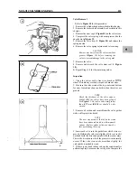
ing it out with an appropriate size drift or
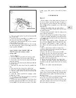
4. Coat the inside diameter of the plug bore and the outer
pin punch. When removing a large core
diameter of the new plug with sealer. Use an oil-resistant
plug, the use of a universal impact slide
sealer if the plug is to be installed in an oil gallery or a
hammer is recommended.
ter-resistant sealer for plugs installed in the water jacket.
5.
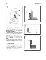
Install the new core plug with an appropriate size core
plug installation tool
(Figure
driver or socket. The
3. Clean the plug bore thoroughly to remove all traces of
outside edge of the plug should be 2-3 mm (0.08-0.12 in.)
the old sealer. Inspect the bore for any damage that might
inside the block.
interfere with proper sealing of the new plug.
6. Repeat Steps 1-5 to replace each remaining core plug.
Table
1 ENGINE SPECIFICATIONS (1
1
Bore
75
(2.95
in.)
Stroke
72
(2.83
in.)
Displacement
cc
(19.4
cu. in.)
Number of cylinders
1
Cylinder bore diameter
75.000-75.030
(2.9528-2.9540
in.)
Bore out-of-round-max.
0.02
mm
(0.0008
in.)
Cylinder block
0.07
(0.0028
in.)
Piston diameter
Standard
74.910-74.940
(2.9492-2.9504
in.)
Wear limit
74.850
mm max.
(2.9468
in.)
Piston top clearance
0.68-0.88
mm
(0.027-0.035
in.)
Piston ring side clearance
Top ring
0.065-0.100
(0.0026-0.0039
in.)
Second ring
0.035-0.070
mm
(0.001 4-0.0028
in.)
Oil ring
0.020-0.055
mm
(0.0008-0.0022
in.)
Ring end gap (all rings)
0.20-0.40
mm
(0.008-0.016
in.)
Piston pin diameter
19.991 -20.000
mm
(0.7870-0.7874
in.)
Piston pin hole diameter
In piston
19.995-20.008
mm
(0.7872-0.7877
in.)
In rod
20.000
mm
(0.7874
in.)
Piston pin clearance
In rod
0.025-0.047
mm
9
in.)
In piston
0.005
tight-0.017 mm loose
(0.0002 in. tight-0.0007
in. loose)
Piston ring width
Top
second ring
1.97-1.99
mm
(0.0776-0.0783
in.)
Oil control ring
3.97-3.99
mm
(0.1563-0.1571
in.)
Crankshaft main
Timing gear end
43.950-43.964
mm
(1.7303-1.7309
in.)
Flywheel end
mm
(2.3602-2.3608
in.)
Journal out-of-round-max.
0.01
(0.0004
in.)
Crankshaft end play
0.06-0.19
(0.0024-0.0075
in.)
Crankshaft runout-max.
0.1 5
mm
(0.006
in.)
Main bearing clearance
Timing gear end
0.036-0.092
(0.0014-0.0036
in.)
Flywheel end
0.036-0.095
(0.0014-0.0037
in.)
Crankshaft thrust
Front
2.75
mm
(0.108
in.)
Inner
2.25
mm
(0.089
in.)
diameter
39.950-39.964
in.)
Journal out-of-round-max.
0.01
(0.0004
in.)
bearing clearance
0.028-0.086
mm
(0.001 1-0.0034
in.)
Connecting rod side clearance
0.2-0.4
mm
(0.008-0.016
in.)
Cylinder head
0.07
mm
(0.003
in.)
Summary of Contents for 1GM10
Page 1: ...YANMAR DIESEL INBOARD SHOP MANUAL ONE TWO 8 THREE CYLINDER ENGINES...
Page 6: ......
Page 7: ......
Page 9: ......
Page 10: ......
Page 11: ......
Page 12: ......
Page 13: ......
Page 16: ......
Page 17: ......
Page 18: ......
Page 19: ......
Page 20: ......
Page 21: ......
Page 22: ......
Page 23: ......
Page 24: ......
Page 25: ......
Page 26: ......
Page 27: ......
Page 28: ...GENERAL INFORMATION 21 Bearing Blocks Press Shaft arm Bearing Spacer Press k 4 bed...
Page 36: ...30 CHAPTER TWO CHARGING SYSTEM TYPICAL Battery switch...
Page 39: ......
Page 44: ...38 CHAPTER TWO LUBRICATION SYSTEM 2GM AND 2GM20 MODELS...
Page 46: ......
Page 50: ......
Page 52: ......
Page 54: ......
Page 55: ......
Page 57: ......
Page 58: ......
Page 64: ......
Page 66: ......
Page 70: ......
Page 71: ......
Page 77: ......
Page 78: ......
Page 79: ......
Page 80: ......
Page 81: ......
Page 82: ......
Page 89: ......
Page 90: ......
Page 91: ......
Page 92: ......
Page 93: ......
Page 94: ......
Page 95: ......
Page 96: ......
Page 97: ......
Page 98: ......
Page 99: ......
Page 100: ......
Page 101: ......
Page 102: ......
Page 112: ...106 CHAPTER SIX...
Page 114: ......
Page 123: ......
Page 124: ......
Page 125: ......
Page 126: ......
Page 129: ......
Page 130: ......
Page 131: ......
Page 133: ......
Page 134: ......
Page 135: ......
Page 136: ......
Page 145: ...FUEL INJECTION AND GOVERNOR SYSTEMS 139 FUEL INJECTION SYSTEM Fuel tank hose fuel pipe...
Page 148: ......
Page 149: ......
Page 150: ......
Page 151: ......
Page 152: ......
Page 153: ......
Page 154: ......
Page 155: ......
Page 156: ......
Page 157: ......
Page 158: ......
Page 165: ......
Page 170: ...164 CHAPTER EIGHT CLOSED COOLING SYSTEM TYPICAL rnlxlng elbow Joint...
Page 172: ......
Page 174: ......
Page 175: ......
Page 176: ......
Page 177: ......
Page 184: ......
Page 190: ......
Page 196: ......
Page 197: ......
Page 201: ......
Page 202: ......
Page 204: ......
Page 205: ......
Page 208: ......
Page 209: ......
Page 219: ......
Page 224: ...218 CHAPTER ELEVEN...
Page 231: ......
Page 235: ......


