MULTICYLINDER ENGINES
105
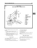
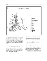
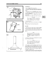
Exhaust
manifold
Cover
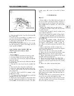
6. Clean any gasket residue from the exhaust manifold
and cylinder head.
7. Remove the exhaust manifold cover retaining screws
and remove the manifold cover (Figure 7).
8. Inspect the exhaust manifold and cover for
carbon buildup and corrosion.
9. Reinstall the exhaust manifold and cover by reversing
the removal procedure. Tighten the retaining nuts to the
torque specified in Table 2.
3HMF and
models with freshwater (closed)
cooling system
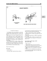
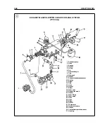
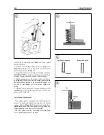
Refer to Figure 6.
1. Refer to Chapter Four and drain the cooling system.
2. Detach the exhaust hose from the exhaust elbow.
3. Remove the water hose from the exhaust manifold and
thermostat housing.
4. Remove the water hose from the exhaust manifold and
freshwater pump.
5. Disconnect the water hoses from the manifold end
caps.
6. Disconnect the water hose to the overflow tank.
7.
Remove the exhaust manifold from the cylinder head.
8. Clean any gasket residue from the exhaust manifold
and cylinder head.
9. Check the exhaust manifold for
carbon
buildup and corrosion.
10. If necessary, refer to Chapter Eight to service the heat
inside the exhaust manifold.
11. Reverse the removal procedure to install the exhaust
manifold. Tighten the manifold bolts to the torque speci-
fied in Table 2. Fill the freshwater section of the closed
cooling
with coolant as described in Chapter
Three.
CYLINDER HEAD
Removal
In some instances, the cylinder head may be removed
for service without removing the engine. If engine re-
moval is necessary, refer to the engine removal procedure.
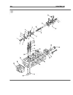
Refer to Figure 8 for an exploded view of the cylinder
head assembly.
To remove the cylinder head, proceed as follows:
1. Disconnect the negative battery cable from the nega-
tive battery terminal.
2. If not previously performed, drain the cooling system
as described in Chapter Four.
3.
Remove the alternator as described in Chapter Eight.
4. Remove the exhaust manifold as previously described.
5 .
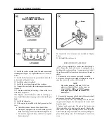
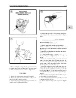
Disconnect the wire lead from the water temperature
sender (Figure 9).
6A. Engines with standard cooling-Disconnect the
lower water hose (Figure 9) from the thermostat housing.
6B. Engines with freshwater (closed) cooling sys-
tem-Remove the freshwater pump as described in Chap-
ter Eight.
7.
Remove the air cleaner and the air cleaner base.
8. Remove the fuel injector and precombustion chamber
as described in Chapter Seven.
9. Remove the valve cover as previously described.
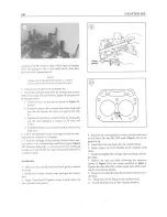
10. Remove the nuts that retain the rocker arm stands
(Figure
then remove the rocker shaft assembly.
11. Remove the push rods and mark them so they can be
reinstalled in their original positions.
12. Detach the oil line fitting from the cylinder head.
13. Unscrew the smaller cylinder head retaining bolts
first, then unscrew the larger bolts and nuts in a crossing
pattern.
14. Remove the cylinder head and head gasket.
Inspection
1.
Refer to the Anticorrosion Maintenance section in
Chapter Three. Remove and inspect the sacrificial anode.
Install the anode in the cylinder head after completing cyl-
inder head service.
2. If service to the valves or rocker assembly is required,
refer to the
and Rocker Assembly sections.
3. Check the cylinder head for signs of oil or water leak-
age before cleaning. Look for corrosion or foreign mate-
rial in the oil and water passages.
Summary of Contents for 1GM10
Page 1: ...YANMAR DIESEL INBOARD SHOP MANUAL ONE TWO 8 THREE CYLINDER ENGINES...
Page 6: ......
Page 7: ......
Page 9: ......
Page 10: ......
Page 11: ......
Page 12: ......
Page 13: ......
Page 16: ......
Page 17: ......
Page 18: ......
Page 19: ......
Page 20: ......
Page 21: ......
Page 22: ......
Page 23: ......
Page 24: ......
Page 25: ......
Page 26: ......
Page 27: ......
Page 28: ...GENERAL INFORMATION 21 Bearing Blocks Press Shaft arm Bearing Spacer Press k 4 bed...
Page 36: ...30 CHAPTER TWO CHARGING SYSTEM TYPICAL Battery switch...
Page 39: ......
Page 44: ...38 CHAPTER TWO LUBRICATION SYSTEM 2GM AND 2GM20 MODELS...
Page 46: ......
Page 50: ......
Page 52: ......
Page 54: ......
Page 55: ......
Page 57: ......
Page 58: ......
Page 64: ......
Page 66: ......
Page 70: ......
Page 71: ......
Page 77: ......
Page 78: ......
Page 79: ......
Page 80: ......
Page 81: ......
Page 82: ......
Page 89: ......
Page 90: ......
Page 91: ......
Page 92: ......
Page 93: ......
Page 94: ......
Page 95: ......
Page 96: ......
Page 97: ......
Page 98: ......
Page 99: ......
Page 100: ......
Page 101: ......
Page 102: ......
Page 112: ...106 CHAPTER SIX...
Page 114: ......
Page 123: ......
Page 124: ......
Page 125: ......
Page 126: ......
Page 129: ......
Page 130: ......
Page 131: ......
Page 133: ......
Page 134: ......
Page 135: ......
Page 136: ......
Page 145: ...FUEL INJECTION AND GOVERNOR SYSTEMS 139 FUEL INJECTION SYSTEM Fuel tank hose fuel pipe...
Page 148: ......
Page 149: ......
Page 150: ......
Page 151: ......
Page 152: ......
Page 153: ......
Page 154: ......
Page 155: ......
Page 156: ......
Page 157: ......
Page 158: ......
Page 165: ......
Page 170: ...164 CHAPTER EIGHT CLOSED COOLING SYSTEM TYPICAL rnlxlng elbow Joint...
Page 172: ......
Page 174: ......
Page 175: ......
Page 176: ......
Page 177: ......
Page 184: ......
Page 190: ......
Page 196: ......
Page 197: ......
Page 201: ......
Page 202: ......
Page 204: ......
Page 205: ......
Page 208: ......
Page 209: ......
Page 219: ......
Page 224: ...218 CHAPTER ELEVEN...
Page 231: ......
Page 235: ......


