8
CHAPTER ONE
to make alignment. Insert a new cotter pin through the nut
and hole, then tap the head lightly to seat it. Bend one arm
over the flat on the nut and the other against the top of the
stud or bolt (Figure 13).
the arms to a suitable length
to prevent them from snagging on clothing or skin. When
the cotter pin is bent and its arms cut to length, it should be
tight. If it can be wiggled, it is improperly installed.
Do not reuse cotter pins, as their ends may break and al-
low the cotter pin to fall out and the fastener to loosen.
Circlips
Circlips can be internal or external design. They are
used to retain items on shafts (external type) or within
tubes (internal type). In some applications, circlips of
varying thickness are used to control the end play of parts
assemblies. These are often called selective circlips. Re-
place circlips during installation, as removal weakens and
deforms them.
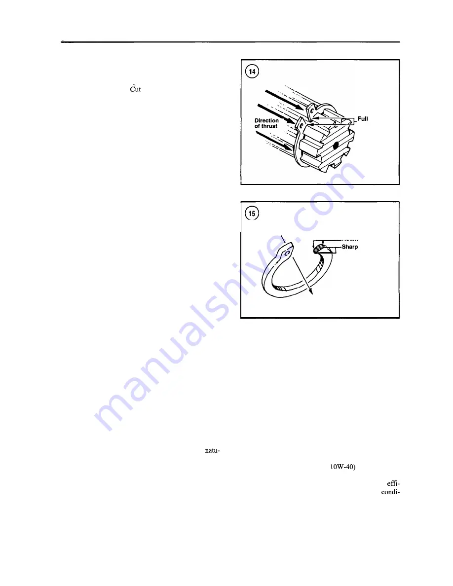
Two basic styles of circlips are available: machined and
stamped circlips. Machined circlips (Figure 14) can be in-
stalled in either direction (shaft or housing) because both
faces are machined, thus creating two sharp edges.
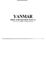
Stamped circlips (Figure 15) are manufactured with one
sharp edge and one rounded edge. When installing
stamped circlips in a thrust situation, the sharp edge must
face away from the part producing the thrust. When in-
stalling circlips, observe the following:
a. Remove and install circlips with circlip pliers. See
Circlip Pliers
in this chapter.
b. Compress or expand circlips only enough to install
them.
c. After the circlip is installed, make sure it is com-
pletely seated in its groove.
LUBRICANTS
Periodic lubrication ensures long life for any type of
equipment. The type of lubricant used is as important as
the lubrication service itself, although in an emergency
the wrong type of lubricant is better than none at all. The
following paragraphs describe the types of lubricants
most often required. Be sure to follow the manufacturer's
recommendations for lubricant types.
Generally, all liquid lubricants are called oil. They may
be mineral-based (including petroleum bases),
ral-based (vegetable and animal bases), synthetic-based
or emulsions (mixtures). Grease is an oil to which a thick-
ening base has been added so that theoend product is
semi-solid. Grease is often classified by the type of thick-
ener added; lithium soap is commonly used.
support
areas
Rounded edges
edges
Direction of thrust
Engine Oil
Oil for marine and automotive four-stroke engines is
classified by the American Petroleum Institute (API) and
the Society of Automotive Engineers (SAE) in several
categories. Oil containers display these classifications on
the top or label. API oil classification is indicated by let-
ters; oils for gasoline engines are identified by an "S" and
oils for diesel engines are identified by a "C".
Viscosity is an indication of the oil's thickness. The
SAE uses numbers to indicate viscosity; thin oils have low
numbers while thick oils have high numbers. A "W" after
the number indicates that the viscosity testing was done at
low temperature to simulate cold-weather operation. En-
gine oils fall into the 5W-30 and 20W-50 range.
Multi-grade oils (for example
are less viscous
(thinner) at low temperatures and more viscous (thicker)
at high temperatures. This allows the oil to perform
ciently across a wide range of engine operating
Summary of Contents for 1GM10
Page 1: ...YANMAR DIESEL INBOARD SHOP MANUAL ONE TWO 8 THREE CYLINDER ENGINES...
Page 6: ......
Page 7: ......
Page 9: ......
Page 10: ......
Page 11: ......
Page 12: ......
Page 13: ......
Page 16: ......
Page 17: ......
Page 18: ......
Page 19: ......
Page 20: ......
Page 21: ......
Page 22: ......
Page 23: ......
Page 24: ......
Page 25: ......
Page 26: ......
Page 27: ......
Page 28: ...GENERAL INFORMATION 21 Bearing Blocks Press Shaft arm Bearing Spacer Press k 4 bed...
Page 36: ...30 CHAPTER TWO CHARGING SYSTEM TYPICAL Battery switch...
Page 39: ......
Page 44: ...38 CHAPTER TWO LUBRICATION SYSTEM 2GM AND 2GM20 MODELS...
Page 46: ......
Page 50: ......
Page 52: ......
Page 54: ......
Page 55: ......
Page 57: ......
Page 58: ......
Page 64: ......
Page 66: ......
Page 70: ......
Page 71: ......
Page 77: ......
Page 78: ......
Page 79: ......
Page 80: ......
Page 81: ......
Page 82: ......
Page 89: ......
Page 90: ......
Page 91: ......
Page 92: ......
Page 93: ......
Page 94: ......
Page 95: ......
Page 96: ......
Page 97: ......
Page 98: ......
Page 99: ......
Page 100: ......
Page 101: ......
Page 102: ......
Page 112: ...106 CHAPTER SIX...
Page 114: ......
Page 123: ......
Page 124: ......
Page 125: ......
Page 126: ......
Page 129: ......
Page 130: ......
Page 131: ......
Page 133: ......
Page 134: ......
Page 135: ......
Page 136: ......
Page 145: ...FUEL INJECTION AND GOVERNOR SYSTEMS 139 FUEL INJECTION SYSTEM Fuel tank hose fuel pipe...
Page 148: ......
Page 149: ......
Page 150: ......
Page 151: ......
Page 152: ......
Page 153: ......
Page 154: ......
Page 155: ......
Page 156: ......
Page 157: ......
Page 158: ......
Page 165: ......
Page 170: ...164 CHAPTER EIGHT CLOSED COOLING SYSTEM TYPICAL rnlxlng elbow Joint...
Page 172: ......
Page 174: ......
Page 175: ......
Page 176: ......
Page 177: ......
Page 184: ......
Page 190: ......
Page 196: ......
Page 197: ......
Page 201: ......
Page 202: ......
Page 204: ......
Page 205: ......
Page 208: ......
Page 209: ......
Page 219: ......
Page 224: ...218 CHAPTER ELEVEN...
Page 231: ......
Page 235: ......


