FUEL INJECTION
AND GOVERNOR SYSTEMS
157
GOVERNOR SPRING
SECONDARY GOVERNOR SPRING
4. If disassembly of the governor shaft assembly is re-
quired, remove the retaining bolts
(29, Figure 47 or Fig-
ure 48) and remove the shaft assembly. To disassemble
the components, detach the snap ring
then drive out
the tapered pins that retain the levers. Replace the worn
parts.
5. Remove the idle adjuster bracket and side cover (4,
Figure 47 or Figure 48).
6. Check the speed control lever and shaft
(12, Figure 47
or
Figure 48) for excessive play between the shaft and the
timing
and between the lever and the shaft.
a. If the shaft is loose in the timing gearcase, remove
the nut
Figure 47 or Figure
then remove
the speed control lever
(3). Remove the shaft (12)
and determine if the shaft, the timing
or
both are worn. Replace or repair the worn part.
b. If the lever is loose on the shaft, remove the nut
(1,
Figure 47 or Figure
then remove the speed
control lever
(3). Determine if the lever, the shaft or
both are worn. Replace any worn parts.
7A. On 1 GM and 1 GMIO models--Check the stop shaft
(5, Figure 47) for excessive play between the shaft and
the timing gearcase. If excessive play is evident, remove
the nut
then withdraw the shaft. Determine if the
shaft, the timing
or both are worn. Replace or re-
pair any worn parts.
7B. On
3HM and
models--Check the stop shaft (5,
Figure 48) for exces-
sive play between the shaft and the timing gearcase. If ex-
cessive play is evident, drive out the taper pin (6) by
driving against the small end of the pin. Remove the lock-
ing screw
(7). Remove the nut
then remove the shaft.
Determine if the shaft, the timing
or both are
worn. Replace or repair any worn parts.
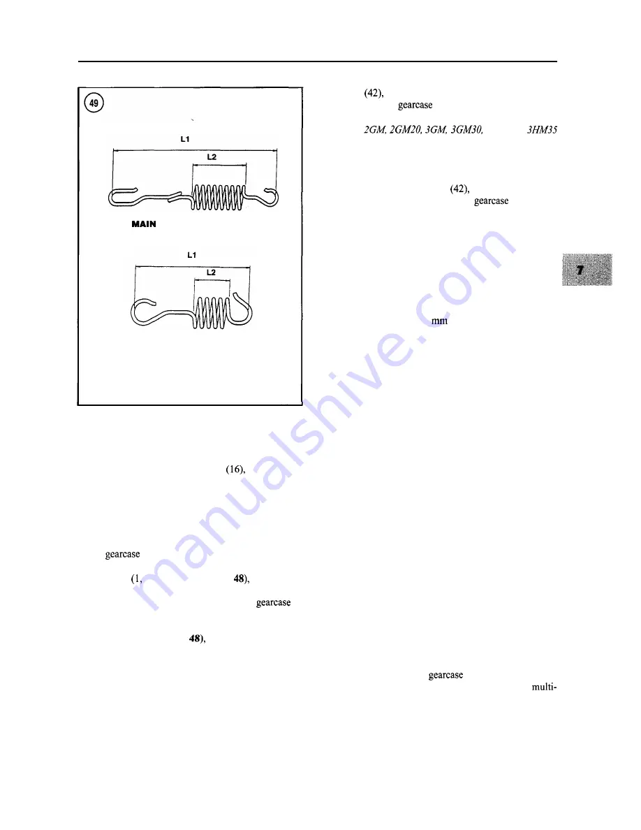
8. Inspect the governor springs for damage and distor-
tion. Measure the length of the main and secondary gover-
nor springs as shown in
Figure 49. Replace either spring
if its free length dimension is not as specified in
Table 2.
If either spring is questionable, take it to a Yanmar dealer-
ship for testing.
9. Remove and inspect the thrust collar (32, Figure 47 or
Figure 48). Replace the thrust collar if damaged or if the
thickness is less than
2.9
(0.114 in.).
10. Remove the thrust bearing (33, Figure 47 or Figure
48). Replace the bearing if damaged.
1 1 . Remove the governor sleeve (34, Figure 47 or Fig-
ure 48). Inspect the governor sleeve and crankshaft for
damage. Refer to the specifications in
Table 3.
12. Check the operation of the flyweight assembly (37,
Figure 47 or Figure 48). The flyweights should move
smoothly without excessive looseness. The contact sur-
face in the flyweight groove should not be excessively
worn. The flyweight assembly must be replaced as a com-
plete assembly. Remove the crankshaft nut as described in
Chapter Five or Six to remove the flyweight assembly.
13. Reassemble the governor assembly by reversing the
disassembly procedure while noting the following:
a. Do not distort the governor springs during installa-
tion.
b. Install the governor springs so the long hook end
engages the speed control lever
(12, Figure 47 or
Figure 48).
c. Install the secondary governor spring
(14, Figure
47 or Figure 48) so the lower end of the spring fits
in the loop on the main governor spring.
d. Note that the pins securing the levers on the shafts
are tapered. The lever should fit tightly on the shaft
after the pin is installed. If not, replace the worn
part.
e. Check the movement of all the parts after assembly.
Motion should be smooth without binding.
14. Reinstall the timing
as described in Chapter
Five for single cylinder engines or Chapter Six for
cylinder engines.
Summary of Contents for 1GM10
Page 1: ...YANMAR DIESEL INBOARD SHOP MANUAL ONE TWO 8 THREE CYLINDER ENGINES...
Page 6: ......
Page 7: ......
Page 9: ......
Page 10: ......
Page 11: ......
Page 12: ......
Page 13: ......
Page 16: ......
Page 17: ......
Page 18: ......
Page 19: ......
Page 20: ......
Page 21: ......
Page 22: ......
Page 23: ......
Page 24: ......
Page 25: ......
Page 26: ......
Page 27: ......
Page 28: ...GENERAL INFORMATION 21 Bearing Blocks Press Shaft arm Bearing Spacer Press k 4 bed...
Page 36: ...30 CHAPTER TWO CHARGING SYSTEM TYPICAL Battery switch...
Page 39: ......
Page 44: ...38 CHAPTER TWO LUBRICATION SYSTEM 2GM AND 2GM20 MODELS...
Page 46: ......
Page 50: ......
Page 52: ......
Page 54: ......
Page 55: ......
Page 57: ......
Page 58: ......
Page 64: ......
Page 66: ......
Page 70: ......
Page 71: ......
Page 77: ......
Page 78: ......
Page 79: ......
Page 80: ......
Page 81: ......
Page 82: ......
Page 89: ......
Page 90: ......
Page 91: ......
Page 92: ......
Page 93: ......
Page 94: ......
Page 95: ......
Page 96: ......
Page 97: ......
Page 98: ......
Page 99: ......
Page 100: ......
Page 101: ......
Page 102: ......
Page 112: ...106 CHAPTER SIX...
Page 114: ......
Page 123: ......
Page 124: ......
Page 125: ......
Page 126: ......
Page 129: ......
Page 130: ......
Page 131: ......
Page 133: ......
Page 134: ......
Page 135: ......
Page 136: ......
Page 145: ...FUEL INJECTION AND GOVERNOR SYSTEMS 139 FUEL INJECTION SYSTEM Fuel tank hose fuel pipe...
Page 148: ......
Page 149: ......
Page 150: ......
Page 151: ......
Page 152: ......
Page 153: ......
Page 154: ......
Page 155: ......
Page 156: ......
Page 157: ......
Page 158: ......
Page 165: ......
Page 170: ...164 CHAPTER EIGHT CLOSED COOLING SYSTEM TYPICAL rnlxlng elbow Joint...
Page 172: ......
Page 174: ......
Page 175: ......
Page 176: ......
Page 177: ......
Page 184: ......
Page 190: ......
Page 196: ......
Page 197: ......
Page 201: ......
Page 202: ......
Page 204: ......
Page 205: ......
Page 208: ......
Page 209: ......
Page 219: ......
Page 224: ...218 CHAPTER ELEVEN...
Page 231: ......
Page 235: ......


