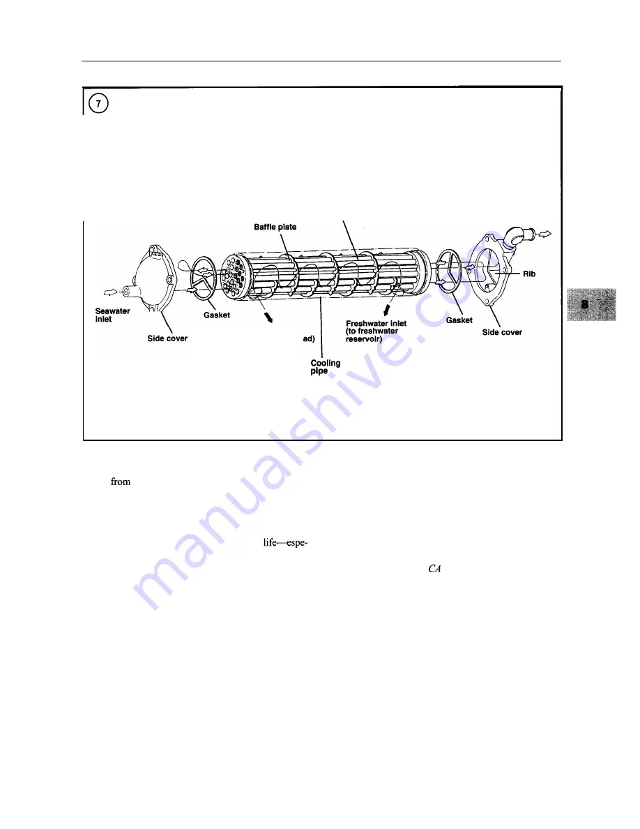
COOLING SYSTEM
165
HEAT EXCHANGER
Cooling tube
Seawater
outlet
Freshwater inlet
(from cylinder he
cover
coolant travels to the heat exchanger, where the heat ab-
sorbed
engine operation passes through the parallel
copper tubes to the water in the seawater system.
Engine cooling is thus accomplished without seawater
entering the engine. This eliminates the corrosion, deposit
buildup and debris accumulation that occurs in a standard
cooling system, resulting in longer engine
cially if the boat is used in saltwater.
Like an automotive cooling system, the freshwater sec-
tion is pressurized at 13 psi. This raises the boiling point
of the coolant to permit higher operating temperatures for
increased engine efficiency.
A thermostat controls coolant circulation. When the
thermostat closes, it prevents coolant from entering the
heat exchanger, rerouting it back to the engine circulating
pump. Once the thermostat opens, it closes off the passage
to the circulating pump and sends the coolant through the
heat exchanger before returning it to the engine pump.
This provides quick engine warm-up and maintains a con-
stant operating temperature.
THERMOSTAT
The thermostat blocks coolant flow to the exhaust man-
ifold (standard cooling) or heat exchanger (closed cool-
ing) when the engine is cold. As the engine warms, the
thermostat gradually opens, allowing coolant to circulate
through the system.
UTZON
Do not operate the engine without
a thermo-
stat. This can lead to serious engine dam-
age.
Thermostats are rated according to their opening tem-
perature. The opening temperature value is stamped on
the thermostat. The thermostat should start to open at the
temperature stamped on the thermostat and should be
fully open at
25" F (14" C) above that temperature. Check
the thermostat rating after removing the thermostat and
compare it to the specifications in Table 2.
Summary of Contents for 1GM10
Page 1: ...YANMAR DIESEL INBOARD SHOP MANUAL ONE TWO 8 THREE CYLINDER ENGINES...
Page 6: ......
Page 7: ......
Page 9: ......
Page 10: ......
Page 11: ......
Page 12: ......
Page 13: ......
Page 16: ......
Page 17: ......
Page 18: ......
Page 19: ......
Page 20: ......
Page 21: ......
Page 22: ......
Page 23: ......
Page 24: ......
Page 25: ......
Page 26: ......
Page 27: ......
Page 28: ...GENERAL INFORMATION 21 Bearing Blocks Press Shaft arm Bearing Spacer Press k 4 bed...
Page 36: ...30 CHAPTER TWO CHARGING SYSTEM TYPICAL Battery switch...
Page 39: ......
Page 44: ...38 CHAPTER TWO LUBRICATION SYSTEM 2GM AND 2GM20 MODELS...
Page 46: ......
Page 50: ......
Page 52: ......
Page 54: ......
Page 55: ......
Page 57: ......
Page 58: ......
Page 64: ......
Page 66: ......
Page 70: ......
Page 71: ......
Page 77: ......
Page 78: ......
Page 79: ......
Page 80: ......
Page 81: ......
Page 82: ......
Page 89: ......
Page 90: ......
Page 91: ......
Page 92: ......
Page 93: ......
Page 94: ......
Page 95: ......
Page 96: ......
Page 97: ......
Page 98: ......
Page 99: ......
Page 100: ......
Page 101: ......
Page 102: ......
Page 112: ...106 CHAPTER SIX...
Page 114: ......
Page 123: ......
Page 124: ......
Page 125: ......
Page 126: ......
Page 129: ......
Page 130: ......
Page 131: ......
Page 133: ......
Page 134: ......
Page 135: ......
Page 136: ......
Page 145: ...FUEL INJECTION AND GOVERNOR SYSTEMS 139 FUEL INJECTION SYSTEM Fuel tank hose fuel pipe...
Page 148: ......
Page 149: ......
Page 150: ......
Page 151: ......
Page 152: ......
Page 153: ......
Page 154: ......
Page 155: ......
Page 156: ......
Page 157: ......
Page 158: ......
Page 165: ......
Page 170: ...164 CHAPTER EIGHT CLOSED COOLING SYSTEM TYPICAL rnlxlng elbow Joint...
Page 172: ......
Page 174: ......
Page 175: ......
Page 176: ......
Page 177: ......
Page 184: ......
Page 190: ......
Page 196: ......
Page 197: ......
Page 201: ......
Page 202: ......
Page 204: ......
Page 205: ......
Page 208: ......
Page 209: ......
Page 219: ......
Page 224: ...218 CHAPTER ELEVEN...
Page 231: ......
Page 235: ......


