ELECTRICAL SYSTEM
187
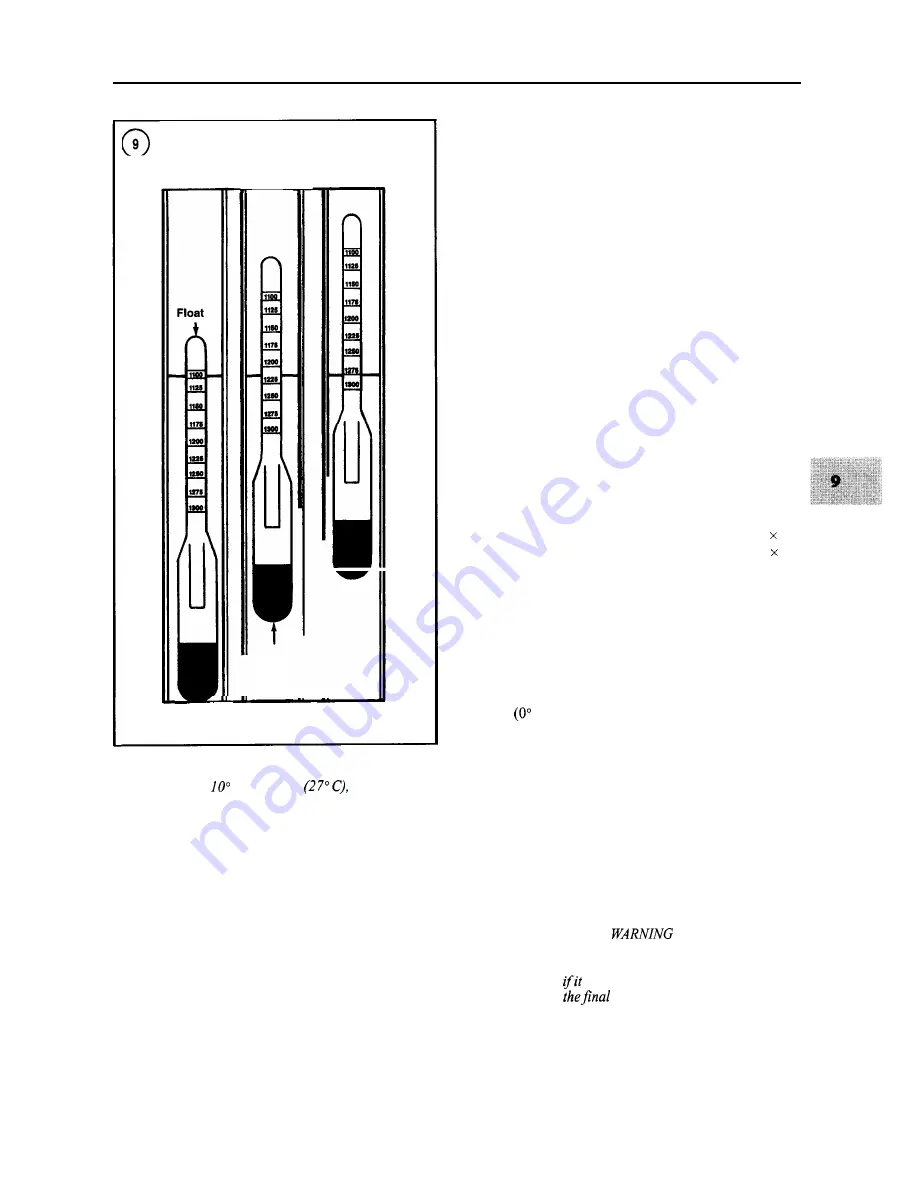
NEEDS
FULLY
DEAD
CHARGING
CHARGED
Weight
For every
below 80" F
subtract
0.004.
Charging
Maintain batteries used for starting in a good state of
charge. Check the battery with a voltmeter as shown in
Figure 10. Recharge any battery that cannot deliver at
least 9.6 volts under a starting load. If recharging does not
bring it up to strength or if it does not hold the charge, re-
place the battery.
A cold battery will not accept a charge readily. If the
temperature is below 40"
F (5" C), allow the battery to
warm up to room temperature before charging. The bat-
tery does not have to be removed from the boat before
charging, but it is a recommended procedure since a
charging battery gives off highly explosive hydrogen gas.
In many boats, the area around the battery is not well ven-
tilated and the gas may remain in the area for several
hours after the charging procedure has been completed.
Sparks or flames occurring near the battery can cause it to
explode, spraying battery acid over a wide area.
Disconnect the negative battery cable first, then the
positive battery cable. Make sure the electrolyte is full.
Remove the vent caps and place a folded paper towel over
the vent openings to absorb any electrolyte that may splat-
ter as the battery charges.
Connect the charger to the battery; negative to negative,
positive to positive. If the charger output is variable, select
a 10-12 amp setting. Set the voltage selector to 12 volts
and plug the charger in. Once the battery starts to accept a
charge, reduce the charge rate to a level that will prevent
excessive gassing.
The length of time required to recharge a battery de-
pends upon its rating, state of charge and temperature.
Generally speaking, the current input time should equal
the battery amp-hour rating. For example, a 45
AH battery
will require a 9-amp charging rate for five hours (9
5
=
45) or a 15-amp charging rate for three hours
(1 5 3
=
45). Check charging progress with the hydrometer.
Jump Starting
If the battery becomes discharged, it is possible to start
and run the engine by jump starting it from another bat-
tery.
Before jump starting a battery when temperatures are
32"
F
C) or lower, check the condition of the electro-
lyte. If it is not visible or if it appears to be frozen, do not
attempt to jump start the battery, as the battery may ex-
plode or rupture.
WARNING
Use extreme caution when connecting a
booster battery to one that is discharged to
avoidpersonal injury or damage to the sys-
tem.
1. Connect the jumper cables in the order and sequence
shown in
Figure 11.
An electrical arc may occur when the final
connection is made. This could cause an ex-
plosion
occurs near the battery. For this
reason,
connection should be made
Summary of Contents for 1GM10
Page 1: ...YANMAR DIESEL INBOARD SHOP MANUAL ONE TWO 8 THREE CYLINDER ENGINES...
Page 6: ......
Page 7: ......
Page 9: ......
Page 10: ......
Page 11: ......
Page 12: ......
Page 13: ......
Page 16: ......
Page 17: ......
Page 18: ......
Page 19: ......
Page 20: ......
Page 21: ......
Page 22: ......
Page 23: ......
Page 24: ......
Page 25: ......
Page 26: ......
Page 27: ......
Page 28: ...GENERAL INFORMATION 21 Bearing Blocks Press Shaft arm Bearing Spacer Press k 4 bed...
Page 36: ...30 CHAPTER TWO CHARGING SYSTEM TYPICAL Battery switch...
Page 39: ......
Page 44: ...38 CHAPTER TWO LUBRICATION SYSTEM 2GM AND 2GM20 MODELS...
Page 46: ......
Page 50: ......
Page 52: ......
Page 54: ......
Page 55: ......
Page 57: ......
Page 58: ......
Page 64: ......
Page 66: ......
Page 70: ......
Page 71: ......
Page 77: ......
Page 78: ......
Page 79: ......
Page 80: ......
Page 81: ......
Page 82: ......
Page 89: ......
Page 90: ......
Page 91: ......
Page 92: ......
Page 93: ......
Page 94: ......
Page 95: ......
Page 96: ......
Page 97: ......
Page 98: ......
Page 99: ......
Page 100: ......
Page 101: ......
Page 102: ......
Page 112: ...106 CHAPTER SIX...
Page 114: ......
Page 123: ......
Page 124: ......
Page 125: ......
Page 126: ......
Page 129: ......
Page 130: ......
Page 131: ......
Page 133: ......
Page 134: ......
Page 135: ......
Page 136: ......
Page 145: ...FUEL INJECTION AND GOVERNOR SYSTEMS 139 FUEL INJECTION SYSTEM Fuel tank hose fuel pipe...
Page 148: ......
Page 149: ......
Page 150: ......
Page 151: ......
Page 152: ......
Page 153: ......
Page 154: ......
Page 155: ......
Page 156: ......
Page 157: ......
Page 158: ......
Page 165: ......
Page 170: ...164 CHAPTER EIGHT CLOSED COOLING SYSTEM TYPICAL rnlxlng elbow Joint...
Page 172: ......
Page 174: ......
Page 175: ......
Page 176: ......
Page 177: ......
Page 184: ......
Page 190: ......
Page 196: ......
Page 197: ......
Page 201: ......
Page 202: ......
Page 204: ......
Page 205: ......
Page 208: ......
Page 209: ......
Page 219: ......
Page 224: ...218 CHAPTER ELEVEN...
Page 231: ......
Page 235: ......


