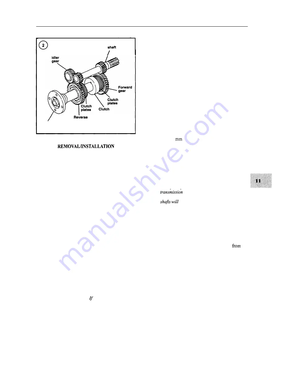
TRANSMISSION-KBW SERIES
217
Input
Reverse
gear
Coupling flange
The following procedure addresses units that are acces-
sible. In some cases, it may be necessary to remove the en-
gine and transmission as a unit before removing the
transmission from the engine. Refer to Chapter Six if en-
gine removal is necessary.
1. If not previously disconnected, disconnect the remote
control cable from the transmission shift lever.
2. If not previously disconnected, disconnect the drive
coupling from the transmission drive flange.
3. Remove the bolts that secure the transmission to the
engine bellhousing.
4. Remove the transmission from the engine.
5. Reinstall the transmission by reversing the removal
procedure. Make sure
to align the splines on the transmis-
sion input shaft and the drive disc during installation.
Tighten the transmission retaining bolts to the torque
specified in Table 2.
OVERHAUL
Refer to Figure 3.
NOTE
Overhaul of the
KB
W transmission requires
special tools, which can be obtained from
Yanmar or fabricated.
the special tools
are not available, have a Yanmar dealership
overhaul the transmission.
Disassembly
1.
Remove the drain plug and drain the transmission oil.
2. Position the transmission in a vise with soft jaws so the
input shaft is held by the vise jaws.
3. The output flange retaining nut is staked. Use a chisel
to cut away the staked portion so the nut will rotate.
4. Install a tool that will prevent rotation of the output
flange.
5. Unscrew the output flange retaining nut.
6. Remove the oil dipstick.
7. Make match marks on the shifter cover and the trans-
mission case so the shifter can be installed in its original
position.
8. Remove the shifter retaining bolts and remove the
shifter assembly.
9. Remove the transmission from the vise.
10. Using an 8
Allen wrench, remove the shift bar re-
taining plug (68, Figure 3) in the rear of the case.
11. Install a 10 mm bolt into the end of the shift bar, then
pull the shift bar (58, Figure 3) out of the case while also
removing the shift fork (57).
12. Remove the transmission mounting flange retaining
bolts.
NOTE
In Step 13, position the transmission so the
input shaft is up when remov-
ing the mountingflange so the transmission
not fall out.
13. Tap on the mounting flange using a soft-faced ham-
mer to dislodge the flange. Position the transmission with
the input shaft up, then remove the flange from the trans-
mission case.
14. Remove the output shaft assembly from the transmis-
sion case and set aside for disassembly.
15. Remove the intermediate shaft assembly
the
transmission case and set aside for disassembly.
16. Remove the input shaft assembly from the transmis-
sion case and set aside for disassembly.
17. Using a large screwdriver, pry out the oil seal in the
transmission case. Be careful not to damage the case or
the adjacent bearing race.
18. Using a large screwdriver, pry out the oil seal in the
transmission mounting flange. Be careful not to damage
the case or the adjacent bearing race.
19. If inspection indicates additional disassembly is nec-
essary, refer to the following sections.
Summary of Contents for 1GM10
Page 1: ...YANMAR DIESEL INBOARD SHOP MANUAL ONE TWO 8 THREE CYLINDER ENGINES...
Page 6: ......
Page 7: ......
Page 9: ......
Page 10: ......
Page 11: ......
Page 12: ......
Page 13: ......
Page 16: ......
Page 17: ......
Page 18: ......
Page 19: ......
Page 20: ......
Page 21: ......
Page 22: ......
Page 23: ......
Page 24: ......
Page 25: ......
Page 26: ......
Page 27: ......
Page 28: ...GENERAL INFORMATION 21 Bearing Blocks Press Shaft arm Bearing Spacer Press k 4 bed...
Page 36: ...30 CHAPTER TWO CHARGING SYSTEM TYPICAL Battery switch...
Page 39: ......
Page 44: ...38 CHAPTER TWO LUBRICATION SYSTEM 2GM AND 2GM20 MODELS...
Page 46: ......
Page 50: ......
Page 52: ......
Page 54: ......
Page 55: ......
Page 57: ......
Page 58: ......
Page 64: ......
Page 66: ......
Page 70: ......
Page 71: ......
Page 77: ......
Page 78: ......
Page 79: ......
Page 80: ......
Page 81: ......
Page 82: ......
Page 89: ......
Page 90: ......
Page 91: ......
Page 92: ......
Page 93: ......
Page 94: ......
Page 95: ......
Page 96: ......
Page 97: ......
Page 98: ......
Page 99: ......
Page 100: ......
Page 101: ......
Page 102: ......
Page 112: ...106 CHAPTER SIX...
Page 114: ......
Page 123: ......
Page 124: ......
Page 125: ......
Page 126: ......
Page 129: ......
Page 130: ......
Page 131: ......
Page 133: ......
Page 134: ......
Page 135: ......
Page 136: ......
Page 145: ...FUEL INJECTION AND GOVERNOR SYSTEMS 139 FUEL INJECTION SYSTEM Fuel tank hose fuel pipe...
Page 148: ......
Page 149: ......
Page 150: ......
Page 151: ......
Page 152: ......
Page 153: ......
Page 154: ......
Page 155: ......
Page 156: ......
Page 157: ......
Page 158: ......
Page 165: ......
Page 170: ...164 CHAPTER EIGHT CLOSED COOLING SYSTEM TYPICAL rnlxlng elbow Joint...
Page 172: ......
Page 174: ......
Page 175: ......
Page 176: ......
Page 177: ......
Page 184: ......
Page 190: ......
Page 196: ......
Page 197: ......
Page 201: ......
Page 202: ......
Page 204: ......
Page 205: ......
Page 208: ......
Page 209: ......
Page 219: ......
Page 224: ...218 CHAPTER ELEVEN...
Page 231: ......
Page 235: ......


