TROUBLESHOOTING
27
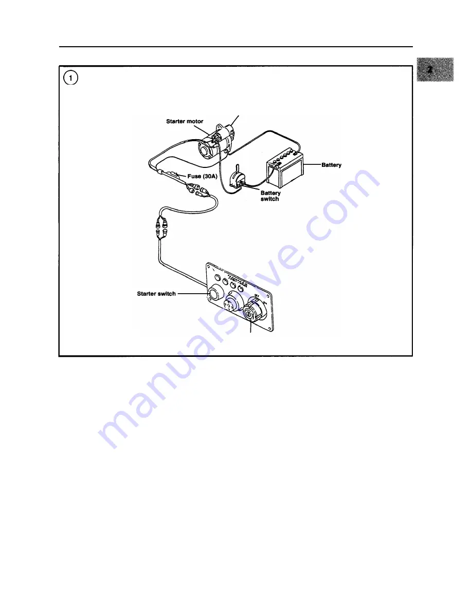
STARTING CIRCUIT (TYPICAL)
Starter solenoid
Key switch
service, as well as to provide a measure of safety that is
STARTING SYSTEM
not required of automotive service. For example, a marine
starter is flashproofed to prevent possible ignition of fuel
vapor in the bilge. The use of an automotive starter as a re-
placement can result in an explosion or fire, which may
cause death, serious injury or boat damage.
This chapter contains brief descriptions of each major
operating system and troubleshooting procedures to be
used. The troubleshooting procedures analyze common
symptoms and provide logical methods of isolation.
These are not the only methods. There may be several ap-
proaches to a problem, but all methods used must have
one thing in common to be successful-a logical, system-
atic approach.
Troubleshooting diagrams for individual systems are
provided within this chapter. A master troubleshooting
chart
(Table 1) is provided at the end of this chapter.
The starting system consists of the battery, starter mo-
tor, starter solenoid, starter switch, key switch, fuse and
connecting wiring. See
Figure 1, typical.
Starting system problems are relatively easy to find. In
many cases, the trouble is a loose or dirty connection.
Starting System Operation
The battery switch, if used, and the key switch must be
in the
ON positions so battery current is available to the
starter circuit. When the start switch on the instrument
panel is pushed, battery current flows to the starter sole-
noid, which mechanically engages the starter with the en-
gine flywheel. The solenoid also directs current to the
starter motor, which rotates the engine flywheel to start
Summary of Contents for 1GM10
Page 1: ...YANMAR DIESEL INBOARD SHOP MANUAL ONE TWO 8 THREE CYLINDER ENGINES...
Page 6: ......
Page 7: ......
Page 9: ......
Page 10: ......
Page 11: ......
Page 12: ......
Page 13: ......
Page 16: ......
Page 17: ......
Page 18: ......
Page 19: ......
Page 20: ......
Page 21: ......
Page 22: ......
Page 23: ......
Page 24: ......
Page 25: ......
Page 26: ......
Page 27: ......
Page 28: ...GENERAL INFORMATION 21 Bearing Blocks Press Shaft arm Bearing Spacer Press k 4 bed...
Page 36: ...30 CHAPTER TWO CHARGING SYSTEM TYPICAL Battery switch...
Page 39: ......
Page 44: ...38 CHAPTER TWO LUBRICATION SYSTEM 2GM AND 2GM20 MODELS...
Page 46: ......
Page 50: ......
Page 52: ......
Page 54: ......
Page 55: ......
Page 57: ......
Page 58: ......
Page 64: ......
Page 66: ......
Page 70: ......
Page 71: ......
Page 77: ......
Page 78: ......
Page 79: ......
Page 80: ......
Page 81: ......
Page 82: ......
Page 89: ......
Page 90: ......
Page 91: ......
Page 92: ......
Page 93: ......
Page 94: ......
Page 95: ......
Page 96: ......
Page 97: ......
Page 98: ......
Page 99: ......
Page 100: ......
Page 101: ......
Page 102: ......
Page 112: ...106 CHAPTER SIX...
Page 114: ......
Page 123: ......
Page 124: ......
Page 125: ......
Page 126: ......
Page 129: ......
Page 130: ......
Page 131: ......
Page 133: ......
Page 134: ......
Page 135: ......
Page 136: ......
Page 145: ...FUEL INJECTION AND GOVERNOR SYSTEMS 139 FUEL INJECTION SYSTEM Fuel tank hose fuel pipe...
Page 148: ......
Page 149: ......
Page 150: ......
Page 151: ......
Page 152: ......
Page 153: ......
Page 154: ......
Page 155: ......
Page 156: ......
Page 157: ......
Page 158: ......
Page 165: ......
Page 170: ...164 CHAPTER EIGHT CLOSED COOLING SYSTEM TYPICAL rnlxlng elbow Joint...
Page 172: ......
Page 174: ......
Page 175: ......
Page 176: ......
Page 177: ......
Page 184: ......
Page 190: ......
Page 196: ......
Page 197: ......
Page 201: ......
Page 202: ......
Page 204: ......
Page 205: ......
Page 208: ......
Page 209: ......
Page 219: ......
Page 224: ...218 CHAPTER ELEVEN...
Page 231: ......
Page 235: ......


