TROUBLESHOOTING
2
9
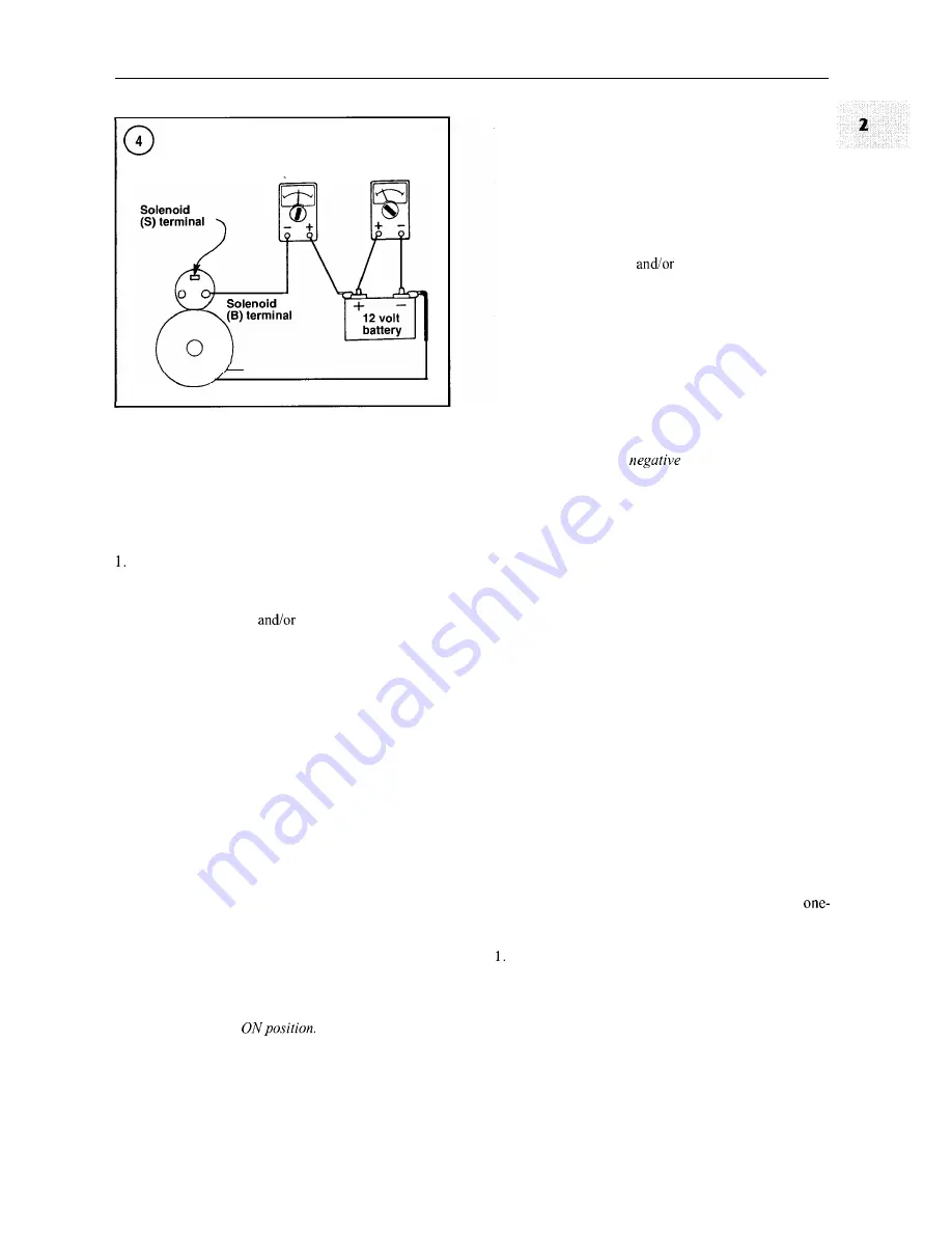
Ammeter
Voltmeter
Starter motor
open circuit or a loose connection. If the engine does not
start, replace the starter solenoid.
Starter spins but does not rotateflywheel
Remove the starter. See Chapter Nine.
2. Check the starter pinion gear. If the teeth are chipped
or worn, inspect the flywheel ring gear for the same prob-
lem. Replace the starter
ring gear as required.
3.
If the pinion gear is in good condition, disassemble the
starter and check the armature shaft for corrosion. See
Brush Replacement, Chapter Nine, for the disassembly
procedure. If no corrosion is found, the starter drive mech-
anism is slipping. Replace the starter with a new or rebuilt
marine unit.
Starter will not disengage when start switch is released
This problem is usually caused by a sticking solenoid or
defective start switch, but the pinion may jam on the fly-
wheel ring gear on an engine with many hours of opera-
tion.
NOTE
A
low battery or loose or corroded battery
connections can also cause the starter to re-
main engaged with the flywheel ring gear:
Low voltage at the starter can cause the
contacts inside the solenoid to chatter and
weld together; resulting in the solenoid
sticking in the
Loud grinding noises when starter runs
This can be caused by improper meshing of the starter
pinion and flywheel ring gear or by a broken overrunning
clutch mechanism.
1.
Remove the starter. See Chapter Nine.
2. Check the starter pinion gear. If the teeth are chipped
or worn, inspect the flywheel ring gear for the same prob-
lem. Replace the starter
ring gear as required.
3.
If the pinion gear is in good condition, the overrunning
clutch mechanism in the starter may be defective. Replace
the starter with a new or rebuilt marine unit.
Starter Solenoid Resistance Tests
Check the starter solenoid using the following resis-
tance tests:
CA
UTION
Disconnect the
battery cable be-
,
fore performing resistance tests.
1.
Refer to Figure
2
and connect an ohmmeter lead to the
S terminal of the solenoid. Connect the remaining ohm-
meter lead to the metal body of the solenoid. The ohmme-
ter should indicate approximately one ohm or less.
Replace the solenoid if the ohmmeter indicates infinite re-
sistance (no continuity).
2. Refer to Figure
3
and connect an ohmmeter lead to the
S terminal of the solenoid. Connect the remaining ohm-
meter lead to the M terminal of the solenoid. The ohmme-
ter should indicate approximately one ohm or less.
Replace the solenoid if the ohmmeter indicates infinite re-
sistance (no continuity).
Starter Motor No-Load Current Draw Test
If troubleshooting indicates that the starter motor may
be defective, use the following starter motor no-load cur-
rent draw test to determine if the starter motor is in accept-
able operating condition.
To perform the test, the following equipment is needed:
an ammeter capable of measuring 0-1 00 amps, a voltme-
ter, a vibration tachometer and a fully charged 12-volt bat-
tery. Minimum battery capacity is 70 amp-hours for
and two-cylinder engines and 100 amp-hours for
three-cylinder engines.
Remove the starter motor from the engine. Securely
fasten the motor in a vise or other suitable holding fixture.
2.
Using a heavy gauge jumper cable, connect the amme-
ter in series with the positive battery terminal (Figure
4).
Connect a voltmeter to the battery.
Summary of Contents for 1GM10
Page 1: ...YANMAR DIESEL INBOARD SHOP MANUAL ONE TWO 8 THREE CYLINDER ENGINES...
Page 6: ......
Page 7: ......
Page 9: ......
Page 10: ......
Page 11: ......
Page 12: ......
Page 13: ......
Page 16: ......
Page 17: ......
Page 18: ......
Page 19: ......
Page 20: ......
Page 21: ......
Page 22: ......
Page 23: ......
Page 24: ......
Page 25: ......
Page 26: ......
Page 27: ......
Page 28: ...GENERAL INFORMATION 21 Bearing Blocks Press Shaft arm Bearing Spacer Press k 4 bed...
Page 36: ...30 CHAPTER TWO CHARGING SYSTEM TYPICAL Battery switch...
Page 39: ......
Page 44: ...38 CHAPTER TWO LUBRICATION SYSTEM 2GM AND 2GM20 MODELS...
Page 46: ......
Page 50: ......
Page 52: ......
Page 54: ......
Page 55: ......
Page 57: ......
Page 58: ......
Page 64: ......
Page 66: ......
Page 70: ......
Page 71: ......
Page 77: ......
Page 78: ......
Page 79: ......
Page 80: ......
Page 81: ......
Page 82: ......
Page 89: ......
Page 90: ......
Page 91: ......
Page 92: ......
Page 93: ......
Page 94: ......
Page 95: ......
Page 96: ......
Page 97: ......
Page 98: ......
Page 99: ......
Page 100: ......
Page 101: ......
Page 102: ......
Page 112: ...106 CHAPTER SIX...
Page 114: ......
Page 123: ......
Page 124: ......
Page 125: ......
Page 126: ......
Page 129: ......
Page 130: ......
Page 131: ......
Page 133: ......
Page 134: ......
Page 135: ......
Page 136: ......
Page 145: ...FUEL INJECTION AND GOVERNOR SYSTEMS 139 FUEL INJECTION SYSTEM Fuel tank hose fuel pipe...
Page 148: ......
Page 149: ......
Page 150: ......
Page 151: ......
Page 152: ......
Page 153: ......
Page 154: ......
Page 155: ......
Page 156: ......
Page 157: ......
Page 158: ......
Page 165: ......
Page 170: ...164 CHAPTER EIGHT CLOSED COOLING SYSTEM TYPICAL rnlxlng elbow Joint...
Page 172: ......
Page 174: ......
Page 175: ......
Page 176: ......
Page 177: ......
Page 184: ......
Page 190: ......
Page 196: ......
Page 197: ......
Page 201: ......
Page 202: ......
Page 204: ......
Page 205: ......
Page 208: ......
Page 209: ......
Page 219: ......
Page 224: ...218 CHAPTER ELEVEN...
Page 231: ......
Page 235: ......


