54
CHAPTER THREE
Freshwater (Closed) Cooling Systems
Inspection
WARNING
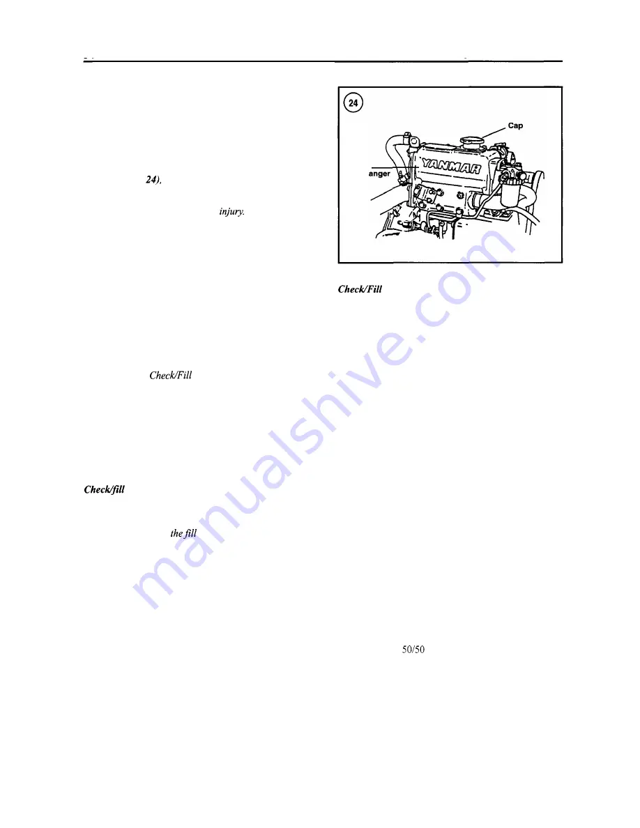
When performing any service work on the
engine or cooling system, never remove the
pressure fill cap on the exhaust manifold
(Figure
drain coolant or disconnect
any hose while the engine is hot. Scalding
fluid and steam may be blown out under
pressure and cause serious
Once a year, or whenever troubleshooting the cooling
system, check the following items. If the proper equip-
ment is not available, have the tests performed by a radia-
tor shop.
1. Loosen and remove the pressure fill cap (Figure
24).
2. Check the cap seals for tears or cracks. Check for a
bent or distorted cap. Rinse the cap under warm tap water
to flush away any loose rust or dirt particles.
3. Inspect the cap neck seat for dents, distortion or con-
tamination. Wipe the sealing surface with a clean cloth to
remove any rust or dirt.
4.
Check the fluid level and fill the system if necessary as
described in the
Coolant section in this chap-
ter.
5.
Check all cooling system hoses for damage or deterio-
ration. Replace any hose that is questionable. Make sure
all hose clamps are tight.
6.
Check the heat exchanger (Figure
25)
for cracks or
damage. Service, if necessary, as described in Chapter
Eight.
coolant (not equipped with
remote reservoir)
WARNING
Do not remove
pressure cap (Figure
24) from the pressurized cooling system
when the engine is hot.
1. Loosen and remove the pressure fill cap (Figure
24).
2. Check the level of fluid in the system. It should be
level with the iron plate at the bottom of the filler neck.
NOTE
Excess coolant (above proper level) will be
expelled when coolant reaches operating
temperature.
3. If the exhaust manifold is not properly filled, add cool-
ant. Refer to the Coolant section in this chapter for proper
coolant.
Heat
exch
Coolant (Equipped With a
Remote Reservoir)
Refer to Figure
26.
1.
Check the level of the coolant in the remote reservoir
tank (Figure 26) when the engine is cold. The coolant
level should be between the marks on the tank.
2. If the coolant level is low, but the tank is not dry, add
coolant to the tank. Refer to the following section for the
proper coolant mixture.
WARNING
Do not remove the pressure fill cap (Figure
24) from the pressurized cooling system
when the engine is hot.
3.
If the coolant level is low, but the tank is dry, remove
the pressure fill cap on the exhaust manifold (Figure
24).
Add coolant to the exhaust manifold so it is full, replace
the cap, then add coolant to the remote reservoir tank to
the proper level.
4. Run the engine until it reaches normal operating tem-
perature, then let the engine cool. Recheck the coolant
level in the remote tank and, if necessary, refill the remote
reservoir tank.
Coolant
Only use a high-quality ethylene glycol-based anti-
freeze designed for aluminum engines. Mix the antifreeze
with water in a
ratio. Coolant capacity is listed in
Table
4.
When mixing antifreeze with water, use only soft
or distilled water. Distilled water can be purchased at su-
permarkets in gallon containers. Do not use tap or salt wa-
ter because it will damage engine parts.
Summary of Contents for 1GM10
Page 1: ...YANMAR DIESEL INBOARD SHOP MANUAL ONE TWO 8 THREE CYLINDER ENGINES...
Page 6: ......
Page 7: ......
Page 9: ......
Page 10: ......
Page 11: ......
Page 12: ......
Page 13: ......
Page 16: ......
Page 17: ......
Page 18: ......
Page 19: ......
Page 20: ......
Page 21: ......
Page 22: ......
Page 23: ......
Page 24: ......
Page 25: ......
Page 26: ......
Page 27: ......
Page 28: ...GENERAL INFORMATION 21 Bearing Blocks Press Shaft arm Bearing Spacer Press k 4 bed...
Page 36: ...30 CHAPTER TWO CHARGING SYSTEM TYPICAL Battery switch...
Page 39: ......
Page 44: ...38 CHAPTER TWO LUBRICATION SYSTEM 2GM AND 2GM20 MODELS...
Page 46: ......
Page 50: ......
Page 52: ......
Page 54: ......
Page 55: ......
Page 57: ......
Page 58: ......
Page 64: ......
Page 66: ......
Page 70: ......
Page 71: ......
Page 77: ......
Page 78: ......
Page 79: ......
Page 80: ......
Page 81: ......
Page 82: ......
Page 89: ......
Page 90: ......
Page 91: ......
Page 92: ......
Page 93: ......
Page 94: ......
Page 95: ......
Page 96: ......
Page 97: ......
Page 98: ......
Page 99: ......
Page 100: ......
Page 101: ......
Page 102: ......
Page 112: ...106 CHAPTER SIX...
Page 114: ......
Page 123: ......
Page 124: ......
Page 125: ......
Page 126: ......
Page 129: ......
Page 130: ......
Page 131: ......
Page 133: ......
Page 134: ......
Page 135: ......
Page 136: ......
Page 145: ...FUEL INJECTION AND GOVERNOR SYSTEMS 139 FUEL INJECTION SYSTEM Fuel tank hose fuel pipe...
Page 148: ......
Page 149: ......
Page 150: ......
Page 151: ......
Page 152: ......
Page 153: ......
Page 154: ......
Page 155: ......
Page 156: ......
Page 157: ......
Page 158: ......
Page 165: ......
Page 170: ...164 CHAPTER EIGHT CLOSED COOLING SYSTEM TYPICAL rnlxlng elbow Joint...
Page 172: ......
Page 174: ......
Page 175: ......
Page 176: ......
Page 177: ......
Page 184: ......
Page 190: ......
Page 196: ......
Page 197: ......
Page 201: ......
Page 202: ......
Page 204: ......
Page 205: ......
Page 208: ......
Page 209: ......
Page 219: ......
Page 224: ...218 CHAPTER ELEVEN...
Page 231: ......
Page 235: ......


