78
CHAPTER FIVE
5. Remove the valve keys (2, Figure 22) and release the
spring tension.
6. Remove the valve spring retainer and valve spring.
CA UTION
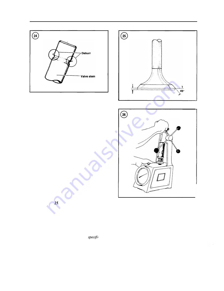
Remove any burrs from the valve stem lock
grooves (Figure 24) before removing the
valve to prevent damage to the valve guide.
7.
Remove the valve.
8. Remove and discard the valve stem seal
(5, Figure
22).
9. Repeat Steps
3-8 for the remaining valve.
Inspection
1. Clean the valves with a fine wire brush or buffing
wheel. Discard any cracked, warped or burned valves.
2.
Measure the valve stems at the top, center and bottom
for wear. A machine shop can do this when the valves are
ground.
NOTE
Check the thickness of the valve edge or
margin after the valves have been ground.
See Figure
Any valve with a margin less
than 0.75 mm (0.030 in.) should be dis-
carded.
3. Remove all carbon and varnish from the valve guides
with a stiff spiral wire brush.
NOTE
The next step assumes that all valve stems
have been measured and are within
cations. Replace valves with worn stems be-
fore performing this step.
Valve head thickness
4.
Insert each valve into the guide from which it was re-
moved. Holding the valve just slightly off its seat, rock it
back and forth in a direction parallel with the rocker arms.
This is the direction in which the greatest wear normally
occurs. If the valve stem rocks more than slightly, the
valve guide is probably worn.
5. If there is any doubt about valve guide condition after
performing Step 4, measure the valve guide. Compare the
results with specifications in
Table 1. Worn guides must
be replaced.
Summary of Contents for 1GM10
Page 1: ...YANMAR DIESEL INBOARD SHOP MANUAL ONE TWO 8 THREE CYLINDER ENGINES...
Page 6: ......
Page 7: ......
Page 9: ......
Page 10: ......
Page 11: ......
Page 12: ......
Page 13: ......
Page 16: ......
Page 17: ......
Page 18: ......
Page 19: ......
Page 20: ......
Page 21: ......
Page 22: ......
Page 23: ......
Page 24: ......
Page 25: ......
Page 26: ......
Page 27: ......
Page 28: ...GENERAL INFORMATION 21 Bearing Blocks Press Shaft arm Bearing Spacer Press k 4 bed...
Page 36: ...30 CHAPTER TWO CHARGING SYSTEM TYPICAL Battery switch...
Page 39: ......
Page 44: ...38 CHAPTER TWO LUBRICATION SYSTEM 2GM AND 2GM20 MODELS...
Page 46: ......
Page 50: ......
Page 52: ......
Page 54: ......
Page 55: ......
Page 57: ......
Page 58: ......
Page 64: ......
Page 66: ......
Page 70: ......
Page 71: ......
Page 77: ......
Page 78: ......
Page 79: ......
Page 80: ......
Page 81: ......
Page 82: ......
Page 89: ......
Page 90: ......
Page 91: ......
Page 92: ......
Page 93: ......
Page 94: ......
Page 95: ......
Page 96: ......
Page 97: ......
Page 98: ......
Page 99: ......
Page 100: ......
Page 101: ......
Page 102: ......
Page 112: ...106 CHAPTER SIX...
Page 114: ......
Page 123: ......
Page 124: ......
Page 125: ......
Page 126: ......
Page 129: ......
Page 130: ......
Page 131: ......
Page 133: ......
Page 134: ......
Page 135: ......
Page 136: ......
Page 145: ...FUEL INJECTION AND GOVERNOR SYSTEMS 139 FUEL INJECTION SYSTEM Fuel tank hose fuel pipe...
Page 148: ......
Page 149: ......
Page 150: ......
Page 151: ......
Page 152: ......
Page 153: ......
Page 154: ......
Page 155: ......
Page 156: ......
Page 157: ......
Page 158: ......
Page 165: ......
Page 170: ...164 CHAPTER EIGHT CLOSED COOLING SYSTEM TYPICAL rnlxlng elbow Joint...
Page 172: ......
Page 174: ......
Page 175: ......
Page 176: ......
Page 177: ......
Page 184: ......
Page 190: ......
Page 196: ......
Page 197: ......
Page 201: ......
Page 202: ......
Page 204: ......
Page 205: ......
Page 208: ......
Page 209: ......
Page 219: ......
Page 224: ...218 CHAPTER ELEVEN...
Page 231: ......
Page 235: ......


