80
CHAPTER FIVE
3.
Remove the cylinder head as described in this chapter.
NOTE
Note the location of the long screw when re-
moving the oil pan retaining screws.
4. Remove the oil pan.
5.
Rotate the crankshaft until the piston is at bottom dead
center. Pack the cylinder bore with clean shop rags. Re-
move the carbon ridge at the top of the cylinder bore with
a ridge reamer. These can be rented for use. Vacuum out
the shavings, then remove the shop rags.
6.
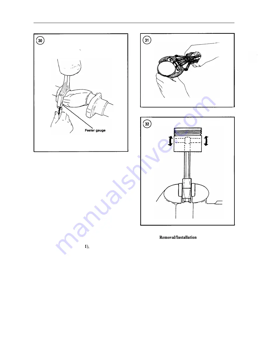
Rotate the crankshaft until the connecting rod is cen-
tered in the bore. Measure the connecting rod side clear-
ance with a flat feeler gauge (Figure 30). If the clearance
exceeds specifications (Table
replace the connecting
rod during reassembly.
7. Remove the connecting rod bolts. Lift off the cap,
along with the lower bearing insert.
8.
Use
a wooden hammer handle to push the piston and
connecting rod from the bore.
9. Remove the piston rings with a ring remover (Figure
31).
Piston Pin
The steel piston pin rides directly in the piston and the
connecting rod bushing. Circlips at each end retain the
piston pin in the piston.
1. Before removing the piston, place the crankshaft end
of the connecting rod in a vise with soft jaws. Rock the
piston as shown in Figure 32. Any rocking motion (do not
confuse with the normal sliding motion) indicates wear on
the piston pin, piston pin bore or connecting rod small end
bore (or a combination of these).
Summary of Contents for 1GM10
Page 1: ...YANMAR DIESEL INBOARD SHOP MANUAL ONE TWO 8 THREE CYLINDER ENGINES...
Page 6: ......
Page 7: ......
Page 9: ......
Page 10: ......
Page 11: ......
Page 12: ......
Page 13: ......
Page 16: ......
Page 17: ......
Page 18: ......
Page 19: ......
Page 20: ......
Page 21: ......
Page 22: ......
Page 23: ......
Page 24: ......
Page 25: ......
Page 26: ......
Page 27: ......
Page 28: ...GENERAL INFORMATION 21 Bearing Blocks Press Shaft arm Bearing Spacer Press k 4 bed...
Page 36: ...30 CHAPTER TWO CHARGING SYSTEM TYPICAL Battery switch...
Page 39: ......
Page 44: ...38 CHAPTER TWO LUBRICATION SYSTEM 2GM AND 2GM20 MODELS...
Page 46: ......
Page 50: ......
Page 52: ......
Page 54: ......
Page 55: ......
Page 57: ......
Page 58: ......
Page 64: ......
Page 66: ......
Page 70: ......
Page 71: ......
Page 77: ......
Page 78: ......
Page 79: ......
Page 80: ......
Page 81: ......
Page 82: ......
Page 89: ......
Page 90: ......
Page 91: ......
Page 92: ......
Page 93: ......
Page 94: ......
Page 95: ......
Page 96: ......
Page 97: ......
Page 98: ......
Page 99: ......
Page 100: ......
Page 101: ......
Page 102: ......
Page 112: ...106 CHAPTER SIX...
Page 114: ......
Page 123: ......
Page 124: ......
Page 125: ......
Page 126: ......
Page 129: ......
Page 130: ......
Page 131: ......
Page 133: ......
Page 134: ......
Page 135: ......
Page 136: ......
Page 145: ...FUEL INJECTION AND GOVERNOR SYSTEMS 139 FUEL INJECTION SYSTEM Fuel tank hose fuel pipe...
Page 148: ......
Page 149: ......
Page 150: ......
Page 151: ......
Page 152: ......
Page 153: ......
Page 154: ......
Page 155: ......
Page 156: ......
Page 157: ......
Page 158: ......
Page 165: ......
Page 170: ...164 CHAPTER EIGHT CLOSED COOLING SYSTEM TYPICAL rnlxlng elbow Joint...
Page 172: ......
Page 174: ......
Page 175: ......
Page 176: ......
Page 177: ......
Page 184: ......
Page 190: ......
Page 196: ......
Page 197: ......
Page 201: ......
Page 202: ......
Page 204: ......
Page 205: ......
Page 208: ......
Page 209: ......
Page 219: ......
Page 224: ...218 CHAPTER ELEVEN...
Page 231: ......
Page 235: ......


