background image

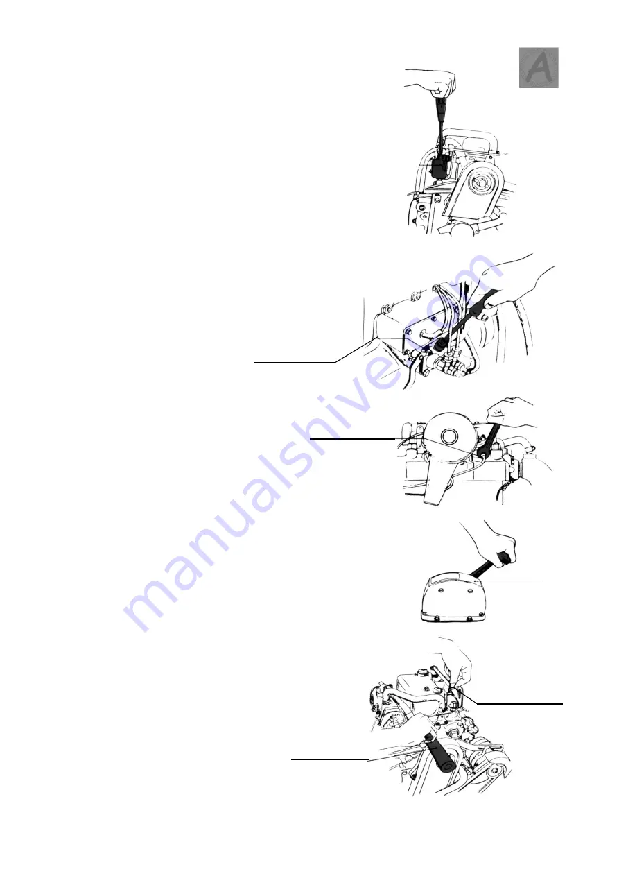
AIR VENTING

1)

Open the fuel cock.

2)

Loosen the air venting plug on the fuel
strainer.
After bubbles stop coming out with the
fuel, tighten again.

3)

Loosen both the fuel joint on the side of
the fuel strainer and the air venting plug
on the fuel injection pump.
And after bubbles stop coming out with
the fuel, tighten the latter plug and then
tighten former.

4)

Remove the nipple on the side of the
injection valve.

5)

Set the speed control lever to
the FULL position.

6)

Disengage the decompression lever and
turn the starting handle about 20 - 30 times
until air in the high pressure line is expelled.

7)

Tighten the nipple on the side of the
injection valve, turn the starting handle
until the sound of fuel injection from the
fuel injection valve is heard.

By this procedure, air can be completely
vented from the fuel line.

VII

14.

Fuel oil strainer

Fuel injection pump

Fuel injection valve

Full

Decompression lever

Starting handle

Summary of Contents for 2 QM 20

Page 1: ...Your on the job Partner MODEL 2 QM 20 3 QM 30 F Y Abma s Jachtwerf Eeltje Baasweg 4 8606 KA Sneek Tel 0515 419065 OPERATION MANUAL ...

Page 2: ...t gas 6 Abnormal sounds Fresh water cooled engine cooling system handling instructions 18 Engine Models 2 QM 20 F 3 QM 30 F For pleasure boat 2 QM 20 Y 3 QM 30 Y For work boat 14 16 1 15 2 5 7 11 12 III PREPARATION IV STARTING I NAME OF PARTS II BEFORE USING THE ENGINE IX VII AIR VENTING VIII PERIODICAL CHECK V VI STOPPING POINTS TO CHECK DURING OPERATION ...

Page 3: ...lutch case Fuel oil strainer Fuel injection pump Rocker cover Cooling water pump F O feed pump Propeller shaft coupling Oil dipstick Speed control lever Intake silencer Gear lever Hoisting bolt Decompression lever Exhaust elbow Clutch case Propeller shaft coupling ...

Page 4: ...l NOTE Presence of water or dust in the fuel may cause failure of the engine and early wear of the plunger fuel injection pump and the fuel injection valve nozzle Water and dust in the fuel tank should be removed and clean fuel used 2 Britisch Petroleum Shell Diesoline or local equivalent CALTEX SHELL MOBIL ESSO B P Caltex Diesel oil Mobil Diesel oil Esso Diesel oil Brand Name II ...

Page 5: ... Energol ICMB Britisch B P Energol DS 3 Petroleum 50 50 20W 20W 40 50 10W 20 3 Recommended brands of lub oil Shell Talona Oil Shell Rimula Oil Shell Rotella Oil SHELL RPM Delo Marine Oil Estor HD Esso Lube HD Standard Diesel Oil 10 W 20 20 W 10 W 20 20 W 20 20 20 SAE NO Supplier Brand Name over 35º C II below 10º C 10 20ºC 20 20 W 50 50 20 20 W 20 35ºC 50 CALTEX 20 20 W 10 W MOBIL 10 W 20 W 40 Del...

Page 6: ...ning in 1 The new engine must be carefully run in during the first 50 hours and not subjected to strain 2 After the running in period retighten any important nuts and bolts that are loose II 4 2 QM 20 5 1 litres 0 5 litres 3 QM 30 7 0 litres 1 2 litres ...

Page 7: ...to the FULL position and the gear lever in NEUTRAL 2 Disengage the decompression lever then turn the starting handle two or three times and listen to the sound of fuel injection 3 If the proper fuel injection sound cannot be heard refer to AIR VENTING on page 14 5 Fuel tank F O cock F O drain cock Starting handle Decompression lever ...

Page 8: ......

Page 9: ... the upper mark on the dipstick NOTE Avoid both overfilling and underfilling The correct oil level can be determined only when the boat is level 2 2 Lubrication of each part 1 Starter chain III 6 Oil dipstick Oil dipstick Upper marking Lower marking Oil dipstick clutch case Oil dipstick crankcase L O supply port L O supply port Chain ...

Page 10: ......

Page 11: ...trol lever to FULL 3 Disengage the decompression lever and turn the starting handle vigorously 5 or 6 times When sufficient momentum has been obtained release the decompression lever and further turn the starting handle firmly IV 7 Gear lever Full Decompression lever Starting handle Neutral ...

Page 12: ......

Page 13: ...ever to NEUTRAL 2 Set the speed control lever to FULL 3 Turn on the battery switch 4 Turn the starter switch to the START position 5 Release the starter switch as soon as the engine starts IV 8 Neutral Gear lever Full Battery switch Key switch ...

Page 14: ...h off while the engine is running 3 Be sure to check that the lub oil pressure warning lamp the cooling water warning lamp and the charging lamp go out 4 When the engine fails to start easily during cold weather operations disengage the decompression lever and turn the starter switch to the START position until the engine gains momentum Then release the decompression lever Wiring Diagram IV 9 ...

Page 15: ... load for at least five minutes 2 If the engine is running normally engage low speed with clutch and then gradually increase speed Check points Oil leakage Water leakage Gas leakage Abnormal sounds Lamps Charging L O warning and C W warning IV 10 Low ...

Page 16: ...er outlet 2 Check that the cooling water warning lamp is out 4 Charging 1 Check that the battery charging lamp is out 5 Exhaust gas 1 Check the colour of the exhaust Excessively black exhaust fumes indicate that the load is too great and should be reduced 6 Abnormal sounds 1 If the engine produces unusual noises during operation stop the engine immediately and check it carefully V 11 Charging lamp...

Page 17: ......

Page 18: ...OPPING 1 Put the gear lever in NEUTRAL let the engine idle then set the speed control lever to STOP NOTE Never use the decompression lever to stop the engine VI 12 Starting handle Stop Decompression lever ...

Page 19: ...he kingstone cock 2 Open the cooling water drain cocks 3 Remove both inlet and outlet hoses from water pump then disassemble the cover to discharge water from inside the water pump After following the above procedure assemble it as before VI 13 Exhaust manifold Cooling water drain cock Cooling water drain cock Cooling water pump Cooling water pump cover Impeller ...

Page 20: ......

Page 21: ...ove the nipple on the side of the injection valve 5 Set the speed control lever to the FULL position 6 Disengage the decompression lever and turn the starting handle about 20 30 times until air in the high pressure line is expelled 7 Tighten the nipple on the side of the injection valve turn the starting handle until the sound of fuel injection from the fuel injection valve is heard By this proced...

Page 22: ......

Page 23: ...Starting shaft A C Generator Lub oil strainer Lub oil pressure warning lamp Intake silencer Exhaust elbow Clutch case Gear lever Starter motor Starting shaft Fuel oil strainer F O feed pump A C Generator Lub oil strainer ...

Page 24: ...ction sound Check oil level in crankcase and clutch case Lubrication starter chain etc Change lub oil in crankcase fig 2 Replace lub oil strainer fig 3 4 Change lub oil in clutch case After operation in cold water Check cooling water circulation Check water pump impeller fig 5 Clean thermostat fig 6 Check anticorrosive zinc fig 7 8 Retighten bolt Adjust intake exhaust valves clearance Clean pre co...

Page 25: ...16 ...

Page 26: ...Fig 9 Fig 4 F O filter element Lub oil filter bowl L O evacuation pump L O evacuation pump Impeller Cooling water pump Thermostat Exhaust mainifold Cooling water pump cover Anticorrosive zinc Antocorrosive zinc Anticorrosive zinc Fuel injection valve ...

Page 27: ......

Page 28: ...Y 3 QM 30 Y for work boat ATTACHED SHEET NO 1 IX 18 Fresh water cooled engine cooling system handling instructions Fresh water inlet Fresh water tank Drain cock Cooling water pump Sea water Fresh water Drain cock Sea water Drain cock Sea water Water mixing elbow ...

Page 29: ......

Page 30: ...rmostat Check cooling water pump Adjust water pump drive belt tension Fresh water side Replace anticorrosive zinc Check pump impeller and casing Check cooling water circulation Sea water side Drain 19 Daily Every 250 hrs Every 300 hrs Every 500 hrs Check and refill ...

Page 31: ...2 Diagram of the cooling water system 20 Fresh water line Sea water line Diagram of the cooling water system Cooling Water Pump Fresh Water Heat Exchanger Cooling pipe Thermostat Anticorrosive zinc ...

Page 32: ... water filter cap is removed after the engine has been stopped and allowed to cool the water level will be 2 3 cm from the top of the filter This is also normal and is caused by the overflow of the unnecessary water as the temperature of the water rises 2 Cooling water fresh water Use clean soft water as the cooling water Hard water will cause calcium build up poor heat transmission and a drop in ...

Page 33: ...fficient pump discharge and the accumulation of scale in the heat exchanger 7 Draining the water To drain the water open the cooling water drain cock and remove the water filter cap If the filter cap is not removed a vacuum will be created in the water jacket and all the water will not drained 8 Idling the engine when stopping Always idle the engine for ten minutes immediately after starting and p...

Page 34: ...hough checking for water and oil leakage during operation is generally necessary check for fresh water leakage with special care Fresh water leakage is directly related to seizing of the engine 11 Anticorrosive zinc Each fresh water cooler is provided with anticorrosion zinc to prevent electrolytic corrosion by the cooling water Replace the anticorrosion zinc after every 500 hours of use Although ...

Page 35: ...water It is therefore recommended that a sub tank be fitted if possible Regarding the handling and installation of the sub tank take note of the following points 1 Installation of sub tank 1 Mount the sub tank at the same height as the clean water tank 2 Ensure that the length of the cooling water tube is no more than 1 m and that it does not break 2 Maintenance during use 1 Check that when the co...

Reviews: