4. Disassembly and Reassembly
86
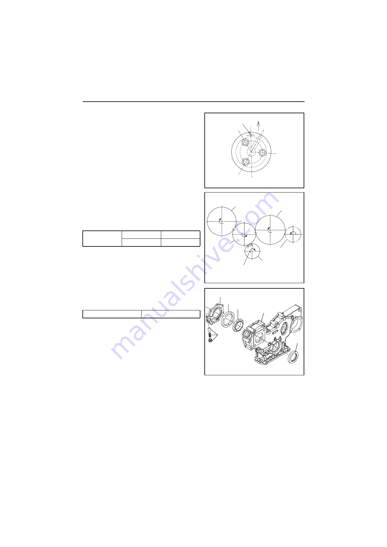
(11) Mounting the idling gear
1) Mount the idling gear so that the oil hole of the idle
gear shaft faces up.
NOTE:
The idle gear shaft must be mounted with the mark
of the shaft upward.
2) Align the “A” and “C” match marks of the idle gear
with the match marks of the camshaft gear and the
crankshaft gear.
3) Measure the idle gear, camshaft gear and
crankshaft gear backlash.
(12) Mounting the lube oil pump
Mount the lube oil pump to the gear case cover.
NOTE:
1) Before installing the outer /inner rotors, coat
them with lube oil (10W30).
2) Assemble the rotor so that the mark of the rotor
may come to the cover side.
3) Confirm that the rotor rotates smoothly.
(13) Mounting the gear case cover
1) Replace the used oil seal with new one. Coat the inside and outside of the oil seals with engine oil
and press fit it into the gear case cover.
2) Apply the liquid gasket to the gear case cover. Position the two knock pins and tighten the bolts of
the gear case cover.
NOTE:
Trim the liquid gasket if it protrudes onto the oil pan mounting surface.
mm
Backlash
Standard
Limit
0.07-0.15
0.17
Tightening torque
N•m(kgf•m)
Flush bolt
5.4-8.4 (0.55-0.86)
(Idle gear shaft)
Upside
Mark
(Gear train)
B
B
A
C
C
Idle gear
Crankshaft gear
Direction of rotation
Fuel injection pump
drive gear
Camshaft gear
Seawater pump
gear
Lube oil pump cover
Outer rotor
Inner rotor
Gear case
Oil seal
Pressure
control valve
(Lube oil pump)


