5. Inspection and Servicing of Basic Engine Parts
109
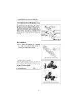
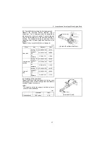
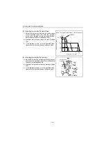
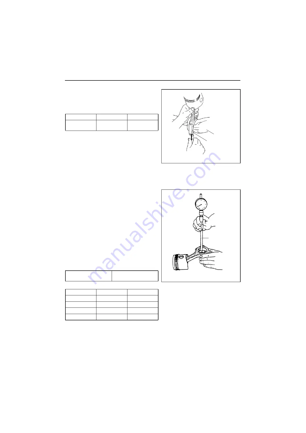
(2) Checking the side clearance of a connecting
rod
Fit the respective crank pins to the connecting rod and
check to make sure that the side clearance in the
crankshaft direction is correct.
5.4.2 Crank pin metal
(1) Checking crank pin metal
Check for flaking, melting or seizure on the contact surface of the crank pin metal.
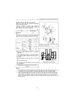
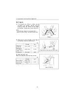
(2) Measuring crank pin oil clearance
Measure the crankpin outside diameter and the crank
pin metal inside diameter. Calculate the oil clearance
from the measured values.
(Refer to 5.5.1(3) for measuring the crank pin outside
diameter.)
Replace the crank pin metal if the oil clearance
becomes about the limit dimension of the below table.
Correct by grinding if unevenly wear, roundness
exceeding the limit or insufficient outside diameter is
found. Also use an undersized metal if necessary.
[NOTICE]
When measuring the inside diameter of the rod big
end, install the crank pin metal in the rod big end not
to mistake the top and bottom of the metals and
tighten the rod bolts by the standard torque.
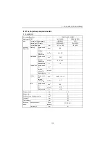
Standard
Limit
Connecting rod
side clearance
0.20-0.40
0.55
N•m(kgf•m)
Rod bolt tightening torque
44.1-49.1
(4.50-5.01)
mm
Item
Standard
Limit
Rod metal I.D.
48.000-48.026
-
Crankpin O.D.
47.952-47.962
47.902
Metal thickness
1.492-1.500
-
Clearance
0.038-0.074
0.150
(Connecting rod side gap)
Crankshaft
Thickness gage
Cylinder gage
(Rod bushing I.D. measurement)


