8. LUBRICATION SYSTEM
142
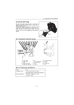
8.2 Lube Oil Pump
8.2.1 Lube oil pump construction
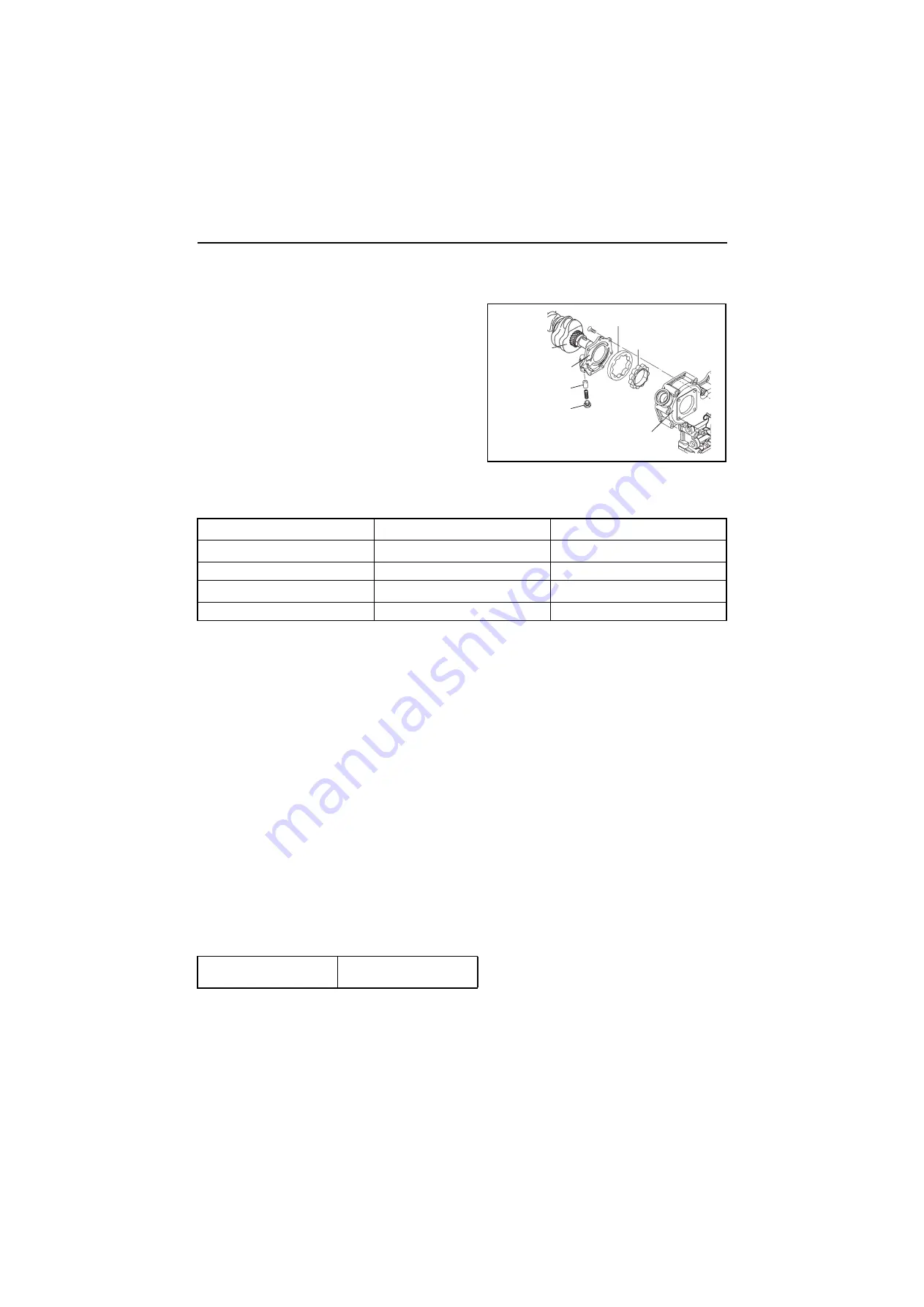
The trochoid type lube oil pump is mounted in the gear
case, and the inner rotor is driven by the crankshaft.
The lube oil flows from the intake filter mounted on the
bottom of the cylinder block through the holes in the
cylinder block and engine plate, and out from the holes
in the engine plate and cylinder block to the discharge
filter.
The lube oil pump is fitted with a control valve, which
controls the discharge pressure at 0.29MPa (3kgf/cm
2
).
8.2.2 Specifications of lube oil pump
8.2.3 Lube oil pump disassembly and reassembly
Disassembly
(1) Remove the crankshaft pulley.
(2) Remove the gear case from the gear case flange.
(3) Remove the lube oil pump cover from the gear case. Do not disassemble the inner /
outer rotors, and check that the pump rotates smoothly.
(4) The oil pressure control valve plug is coated with adhesive and screwed in, so it cannot
be disassembled. These parts cannot be reused after disassembly.
Replace if necessary as an assembly.
Reassembly
[NOTICE]
Always check if the pump rotates smoothly after installation on the gear case.
Running the engine when the pump rotation is heavy may cause the pump to be burnt.
(1) Apply lube oil to rotor (outer/inner) insertion part.
(2) Assemble the outer rotor so that the mark of the end face may become a cover side when inserting
it in the gear case.
(3) Fasten the pump cover by the standard torque.
(4) When replacing the lube oil pump, replace the whole assy.
Lube oil pump specifications
Engine speed
3000 (min
-1
)
800 (min
-1
)
Pump speed
3000 (min
-1
)
772 (min
-1
)
Delivery quantity
º
17.5 (l/min)
º
8.0 (l/min)
Delivery pressure
0.39-0.54MPa (4.0-5.5kgf/cm
2
)
º
0.06MPa (0.6kgf/cm
2
)
Oil temp.
¹
115 (°C)
Tightening torque
5.4-8.4 N•m
(0.55-0.85 kgf•m)
Outer rotor
Inner rotor
Control valve
Crankshaft
Pump cover
Gear case
Plug

