4JH4-HTE
(1)
(2)
(6)
(5)
(3)
(4)
0004560
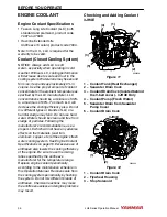
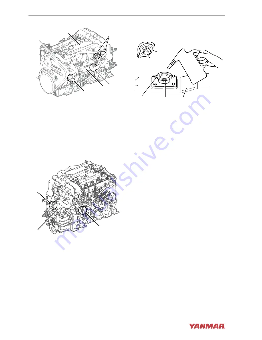
Figure 17
1 – Coolant Tank (Heat Exchanger)
2 – Coolant Pump (Fresh Water)
3 – Seawater Drain from Seawater
Pump Cover
4 – Coolant Drain Cock
5 – Intercooler
6 – Seawater Drain Cock
4JH4-HTE
0004561
(1)
(2)
(3)
Figure 18
1 – Coolant Drain Cock
2 – Seawater Drain Cock
3 – Marine Gear Cooler
Note: The drain cocks are opened before
shipping from the factory. Marine gear
ZF25A does not have a drain cock on the
clutch cooler.
1. Ensure all drain cocks are closed.
2. Loosen the filler cap of the coolant tank
to relieve the pressure then remove the
filler cap.
(2)
(1)
(4)
(3)
0004492
Figure 19
1 – Coolant Filler Cap
2 – Filler Cap Tabs
3 – Filler Port Notches
4 – Coolant Tank
3. Pour coolant slowly into the coolant
tank (Figure 19, (4)) to avoid air
bubbles. Fill until coolant overflows
from the filler port.
4. Align filler cap tabs (Figure 19, (2))
with filler port notches
(Figure 19, (3)) and tighten filler cap
(Figure 19, (1)).
Note: The coolant level rises in the coolant
recovery tank during operation. After
stopping the engine, the coolant will cool
down and the extra coolant will return to the
coolant tank.
BEFORE YOU OPERATE
38
JH4 Series Operation Manual
Summary of Contents for 3JH4E
Page 1: ...JH4 series OPERATION MANUAL 3JH4E 4JH4AE 4JH4 TE 4JH4 HTE P N 0AJH4 G00102 MARINE ENGINES ...
Page 18: ...This Page Intentionally Left Blank SAFETY 12 JH4 Series Operation Manual ...
Page 48: ...This Page Intentionally Left Blank BEFORE YOU OPERATE 42 JH4 Series Operation Manual ...
Page 56: ...This Page Intentionally Left Blank ENGINE OPERATION 50 JH4 Series Operation Manual ...
Page 82: ...This Page Intentionally Left Blank PERIODIC MAINTENANCE 76 JH4 Series Operation Manual ...
Page 101: ...This Page Intentionally Left Blank SPECIFICATIONS JH4 Series Operation Manual 95 ...
Page 134: ...This Page Intentionally Left Blank SYSTEM DIAGRAMS 128 JH4 Series Operation Manual ...
Page 142: ...136 JH4 Series Operation Manual ...


