background image


4TNV106 
4TNV106T

4TNV94L
4TNV98 
4TNV98T

3TNV82A 
3TNV84(T)

4TNV84(T)

3TNV88

4TNV88 


Summary of Contents for 3TNV Series

Page 1: ...4TNV106 4TNV106T 4TNV94L 4TNV98 4TNV98T 3TNV82A 3TNV84 T 4TNV84 T 3TNV88 4TNV88 ...

Page 2: ...is manual assumes the standard type engine the specifications and components may partially be different from the engine installed on individual work equipment power generator pump compressor etc Please also refer to the service manual for each work equipment for details The specifications and components may be subject to change for improvement of the engine quality without notice If any modificati...

Page 3: ...he manual Sufficient consideration for safety is required in addition to the matters marked Especially for safety precautions in a repair or maintenance job not described in this manual receive instructions from a knowledgeable leader Safety marks used in this manual and their meanings are as follows DANGER indicates an imminently hazardous situation which if not avoided WILL result in death or se...

Page 4: ...us level and free from holes in the floor to prevent slip or trip and fall type accidents Bright Safely Illuminated Area The work area should be well lit or illuminated in a safe manner For work in enclosed or dark areas a drop cord should be utilized The drop cord must have a wire cage to prevent bulb breakage and possible ignition of flammable substances Safety Equipment Fire extinguisher s firs...

Page 5: ...ing strap as an attaching device Do not use rope serious injury may result To hold or support an engine secure the engine to a support stand test bed or test cart designed to carry the weight of the engine Do not overload this device serious injury may result Never run an engine without being properly secured to an engine support stand test bed or test cart serious injury may result Appropriate To...

Page 6: ...any other form of ignition away Explosion may occur causing severe personal injury Battery Electrolyte Batteries contain sulfuric acid Do NOT allow it to come in contact with clothing skin and or eyes severe burns will result 7 WASTE MANAGEMENT Observe the following instructions with regard to hazardous waste disposal Negligence of these will have a serious impact on environmental pollution concer...

Page 7: ...efore attempting to approach the unit Rotating Parts Be careful around moving rotating parts Loose clothing jewelry ties or tools may become entangled causing damage to the engine and or severe personal injury Preventing burns from scalding 1 2 Never open the radiator filler cap shortly after shutting the engine down Steam and hot water will spurt out and seriously burn you Allow the engine to coo...

Page 8: ...be used again shall be washed and cleaned sufficiently Select especially clean locations and use clean tools for disassembly of hydraulic units such as the fuel injection pump 5 Precautions for Inspection and Measurement Inspect and measure parts to be used again as required to determine whether they are reusable or not 6 Precautions for Reassembly Reassemble correct parts in correct order accordi...

Page 9: ...n the explanation for each point detailed operation method information standard and precautions are described Description Example The job contents are described in the disassembly procedure for Nos not shown in the illustration Disassembly procedure 1 Follow steps 1 to 15 of the cylinder head disassembly procedure 2 Remove the cooling water pump 3 Remove the crankshaft pulley Point 1 Operation poi...

Page 10: ...e an accident Always observe it Standard Allowable range for inspection and adjustment Limit The maximum or minimum value that must be satisfied during inspection or adjustment 4 Abbreviations Abbreviation Meaning Abbreviation Meaning Assy assembly T D C top dead center Sub Assy sub assembly B D C bottom dead center a T D C after top dead center OS oversize b T D C before top dead center US unders...

Page 11: ...aily Operation 23 2 2 2 inspection after initial 50 hours operation 25 2 2 3 Inspection every 50 hours 28 2 2 4 Inspection every 250 hours or 3 months 32 2 2 5 Inspection every 500 hours or 6 months 35 2 2 6 Inspection every 1 000 hours or one year 37 2 2 7 Inspection every 2000 hours or 2 years 46 2 3 Adjusting the no load maximum or minimum speed 49 2 4 Sensor Inspection 50 2 4 1 Oil pressure sw...

Page 12: ...easurement 76 4 2 6 Valve seat correction 80 4 2 7 Valve guide replacement 81 4 2 8 Valve stem seal replacement 82 4 3 Gear Train and Camshaft 83 4 3 1 Components 83 4 3 2 Disassembly procedure 83 4 3 3 Reassembly procedure 83 4 3 4 Servicing points 84 4 3 5 Parts inspection and measurement 87 4 3 6 Oil seal replacement Gear case side 89 4 3 7 Camshaft bushing replacement 89 4 4 Cylinder Block 90 ...

Page 13: ...system diagram 114 7 2 2 External view and components 115 7 2 3 Disassembly procedure 115 7 2 4 Assembly procedure 116 7 2 5 Servicing points 116 8 TURBOCHAGER Disassembly inspection and reassembly 118 8 1 Structure and Functions 118 8 1 1 Main specifications 118 8 1 2 Construction 118 8 1 3 Structural and functional outline 119 8 1 4 Components 120 8 2 Service Standards and Tightening Torque 121 ...

Page 14: ...response starting of turbocharger 139 8 8 6 Abnormal sound or vibration 139 9 STARTING MOTOR 140 9 1 For 4TNV94L 98 140 9 1 1 Specifications 140 9 1 2 Components 141 9 1 3 Troubleshooting 142 9 1 4 Names of parts and disassembly procedure 143 9 1 5 Inspection and Maintenance 147 9 1 6 Service standards 152 9 1 7 Assembly 153 9 1 8 Characteristic test 155 9 2 For 4TNV106 T 156 9 2 1 Specifications ...

Page 15: ...rent limiter 183 11 2 4 Section area and resistance of electric wire 184 12 SERVICE STANDARDS 185 12 1 Engine Tuning 185 12 2 Engine Body 186 12 2 1 Cylinder head 186 12 2 2 Gear train and camshaft 189 12 2 3 Cylinder block 190 12 3 Lubricating Oil System Trochoid Pump 195 12 3 1 Outside clearance of outer rotor 195 12 3 2 Side clearance of outer rotor 195 12 3 3 Inside clearance of inner rotor 19...

Page 16: ...ion described in the engine specifications tables the next page and after is for standard engine To obtain the information for the engine installed in each machine unit refer to the manual provided by the equipment manufacturer 2 Engine rating conditions are as follows SAE J1349 ISO 3046 1 Atmospheric condition Room temp 25 Atmospheric press 100 kPa 750mm Hg Relative humidity 30 Fuel temp 25 Fuel ...

Page 17: ...Power take off Flywheel Direction of rotation Counterclockwise viewed from flywheel Cooling system Radiator Lubrication system Forced lubrication with trochoid pump Starting system Electric Applicable fuel Diesel oil ISO 8217 DMA BS 2869 A1 or A2 Cetane No 45 min Applicable lubricant API grade class CD or CF Total L 3 6 5 5 Lubricant capacity oil pan Effective L 1 2 2 2 Coolant water capacity engi...

Page 18: ...l side Power take off Flywheel Direction of rotation Counterclockwise viewed from flywheel Cooling system Radiator Lubrication system Forced lubrication with trochoid pump Starting system Electric Applicable fuel Diesel oil ISO 8217 DMA BS 2869 A1 or A2 Cetane No 45 min Applicable lubricant API grade class CD Total L 6 7 Lubricant capacity oil pan Effective L 1 9 Coolant water capacity engine only...

Page 19: ... off Flywheel Direction of rotation Counterclockwise viewed from flywheel Cooling system Radiator Lubrication system Forced lubrication with trochoid pump Starting system Electric Applicable fuel Diesel oil ISO 8217 DMA BS 2869 A1 or A2 cetane No 45 min Applicable lubricant API grade class CD or CF Total L 6 7 Lubricant capacity oil pan Effective L 1 9 Coolant water capacity engine only L 2 0 Over...

Page 20: ...e Power take off Flywheel Direction of rotation Counterclockwise viewed from flywheel Cooling system Radiator Lubrication system Forced lubrication with trochoid pump Starting system Electric Applicable fuel Diesel oil ISO 8217 DMA BS 2869 A1 or A2 Cetane No 45 min Applicable lubricant API grade class CD or CF Total L 4 7 7 2 Lubricant capacity oil pan Effectiv e L 1 8 3 5 Coolant water capacity e...

Page 21: ...ide Power take off Flywheel Direction of rotation Counterclockwise viewed from flywheel Cooling system Radiator Lubrication system Forced lubrication with trochoid pump Starting system Electric Applicable fuel Diesel oil ISO 8217 DMA BS 2869 A1 or A2 cetane No 45 min Applicable lubricant API grade class CD or CF Total L 7 4 Lubricant capacity oil pan Effective L 2 3 Coolant water capacity engine o...

Page 22: ... side Power take off Flywheel Direction of rotation Counterclockwise viewed from flywheel Cooling system Radiator Lubrication system Forced lubrication with trochoid pump Starting system Electric Applicable fuel Diesel oil ISO 8217 DMA BS 2869 A1 or A2 Cetane No 45 min Applicable lubricant API grade class CD or CF Total L 7 4 Lubricant capacity oil pan Effective L 3 4 Coolant water capacity engine...

Page 23: ...e Power take off Flywheel Direction of rotation Counterclockwise viewed from flywheel Cooling system Radiator Lubrication system Forced lubrication with trochoid pump Starting system Electric Applicable fuel Diesel oil ISO 8217 DMA BS 2869 A1 or A2 cetane No 45 min Applicable lubricant API grade class CD or CF Total L 5 8 8 6 Lubricant capacity oil pan Effective L 2 3 4 2 Coolant water capacity en...

Page 24: ...otation Counterclockwise viewed from flywheel Cooling system Radiator Lubrication system Forced lubrication with trochoid pump Starting system Electric Applicable fuel Diesel oil ISO 8217 DMA BS 2869 A1 or A2 Cetane No 45 min Applicable lubricant API grade class CD or CF Total L 10 2 Lubricant capacity oil pan Effective L 4 5 Coolant water capacity engine only L 4 2 Overall length mm 719 Overall w...

Page 25: ...ation Counterclockwise viewed from flywheel Cooling system Radiator Lubrication system Forced lubrication with trochoid pump Starting system Electric Applicable fuel Diesel oil ISO 8217 DMA BS 2869 A1 or A2 Cetane No 45 min Applicable lubricant API grade class CD or CF Total L 10 2 Lubricant capacity oil pan Effective L 4 5 Coolant water capacity engine only L 4 2 Overall length mm 719 Overall wid...

Page 26: ...ction of rotation Counterclockwise viewed from flywheel Cooling system Radiator Lubrication system Forced lubrication with trochoid pump Starting system Electric Applicable fuel Diesel oil ISO 8217 DMA BS 2869 A1 or A2 cetane No 45 min Applicable lubricant API grade class CD or CF Total L 10 2 Lubricant capacity oil pan Effective L 4 5 Coolant water capacity engine only L 4 2 Overall length mm 715...

Page 27: ... viewed from flywheel Cooling system Radiator Lubrication system Forced lubrication with trochoid pump Starting system Electric Applicable fuel Diesel oil ISO 8217 DMA BS 2869 A1 or A2 Cetane No 45 min Applicable lubricant API grade class CD or CF Total L 14 0 Lubricant capacity oil pan Effective L 9 0 7 5 Coolant water capacity engine only L 6 0 Overall length mm 808 776 Overall width mm 629 629 ...

Page 28: ...l Cooling system Radiator Lubrication system Forced lubrication with trochoid pump Starting system Electric Applicable fuel Diesel oil ISO 8217 DMA BS 2869 A1 or A2 Cetane No 45 min Applicable lubricant API grade class CD or CF Total L 14 0 Lubricant capacity oil pan Effective L 9 0 7 5 Coolant water capacity engine only L 6 0 Overall length mm 808 776 Overall width mm 629 628 6 Engine dimensions ...

Page 29: ...ial Standard JIS No K2204 2 Fuel cetane number should be 45 or greater 2 Fuel handling Water and dust in the fuel oil can cause operation failure Use containers which are clean inside to store fuel oil Store the containers away from rain water and dust Before supplying fuel let the fuel container rest for several hours so that water and dust in the fuel are deposited on the bottom Pump up only the...

Page 30: ... Use clean soft water and be sure to add the Long Life Coolant Antifreeze LLC in order to prevent rust built up and freezing If there is any doubt over the water guality distilled water or pre mixed coolant should be used The coolants antifreezes which are good performance for example are shown below TEXACO LONG LIFE COOLANT ANTIFREEZE both standard and pre mixed Product codes 7997 and 7998 HAVOLI...

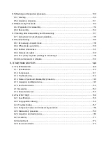
Page 31: ...1 General 1 4 Engine External Views 16 ...

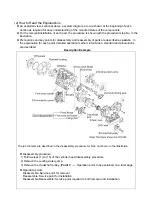
Page 32: ...1 General 1 5 Structural Description 17 ...

Page 33: ...ier 1 2000 10 5 7 8 8 0 6 0 1 0 0 75 kW 8 hp 11 Tier 2 2005 7 5 5 6 8 0 6 0 0 80 0 60 Tier 1 2000 9 5 7 1 6 6 4 9 0 80 0 60 8 kW 19 11 hp 25 Tier 2 2005 7 5 5 6 6 6 4 9 0 80 0 60 Tier 1 1999 9 5 7 1 5 5 4 1 0 80 0 60 19 kW 37 25 hp 50 Tier 2 2004 7 5 5 6 5 5 4 1 0 60 0 45 Tier 1 1998 9 2 6 9 Tier 2 2004 7 5 5 6 5 0 3 7 37 kW 75 50 hp 100 Tier 3 2008 4 7 3 5 5 0 3 7 0 40 0 30 Tier 1 1997 9 2 6 9 Ti...

Page 34: ...1 6 2 Engine identification 1 Emission control labels of US EPA EPA label for constant speed engines EPA label for variable speed engines 2 Emission control label for both EPA and ARB 3 97 68EC Directive label 19 ...

Page 35: ... Requirement on engine installation condition a Intake air depression kPa mmAq Initial Permissible 2 9 300 6 23 635 b Exhaust gas back pressure kPa mmAq Engine type Initial Permissible Naturally aspirated engines 12 7 1300 15 3 1560 4TNV98T 4TNV106T 9 8 1000 11 7 1200 3 4TNV84T 4 9 500 5 9 600 2 Fuel oil and lubricating oil a Fuel The diesel fuel oil US No 2 diesel fuel oil b Lube oil API grade cl...

Page 36: ...s or years shown in the table come first in the condition that the maintenance inspection was carried out based on the List of Periodic Inspections Maintenance period Quality Guarantee Period Parts Power Rating Fuel nozzle cleaning Adjustment cleaning repairs for fuel nozzle fuel pump turbocharger electronic control unit etc For nozzle fuel pump turbocharger 37 kW 130 Every 1500 hours applied from...

Page 37: ...system Lube oil filter replacement 1 st time 2 nd time and thereafter Coolant water level check and replenishment Radiator fin cleaning V belt tension check 1 st time 2 nd time and thereafter Coolant water replacement Cooling water system Coolant water path flushing and maintenance Rubber house Fuel pipe and coolant water pipe inspection and maintenance Governor Inspection and adjustment of govern...

Page 38: ... leak from the cooling water system Damaged parts Loosened or lost bolts Fuel radiator rubber hoses V belt cracked loosened clamp 2 Fuel tank level check and fuel supply Check the remaining fuel oil level in the fuel tank and refuel the recommended fuel if necessary Refer to 1 3 1 3 Lube oil level check and replenishment a Checking oil level Check the lube oil level with the dipstick after adjusti...

Page 39: ...team and hot water will spurt out and seriously burn you Wait until the radiator is cooled down after the engine has stopped wrap the filler cap with a rag piece and turn the cap slowly to gently release the pressure inside the radiator Securely tighten the filler cap after checking the radiator Steam can spurt out during operation if the cap is tightened loosely a Checking coolant water volume Ch...

Page 40: ... one Check the loosened clamp If found tighten it 6 Inspection and adjustment of governor lever and accelerator Make sure the accelerator of the machine unit can be operated smoothly before starting the engine If it feels heavy to manipulate lubricate the accelerator cable joints and pivots Adjust the accelerator cable if there is a dislocation or excessive play between the accelerator and the gov...

Page 41: ...ube oil filter counter clockwise using a filter wrench customer procured to remove it Clean the mounting face of the oil filter Moisten the new oil filter gasket with the engine oil and install the new engine oil filter manually turning it clockwise until it comes into contact with the mounting surface and tighten it further to 3 4 of a turn with the filter wrench Tightening torque 20 24N m 2 0 2 ...

Page 42: ...hever you can easily carry out the check and adjustment on the machine unit New V belt refers to a V belt which has been used less than 5 minutes on a running engine Used V belt refers to a V belt which has been used on a running engine for 5 minutes or more The specified deflection to be measured at each position should be as follows Unit mm Direction A B C For used V belt 10 14 7 10 9 13 For new...

Page 43: ...parator is made from semi transparency material and in the cup the red colored float ring which rises on the surface of the drain is installed to visualize the amoun of drain Also the water separator with sensor to detect the drain for warning device on a controle panel is provided as the ptional o Drain off the water separator in the following manner 1 Prepare a waste oil container 2 Close the fu...

Page 44: ...ter mounting Move the priming pump up and down to feed fuel until feel your hand slightly heavy 4 Battery electrolyte level check and battery recharging Fire due to electric short circuit Make sure to turn off the battery switch or disconnect the negative cable before inspecting the electrical system Failure to do so could cause short circuiting and fires Always disconnect the Negative battery cab...

Page 45: ...place the battery Remove the battery from the battery mounting of the machine unit after daily use if letting the machine unit leave in the place that the ambient temperature could drop at 15 or less And store the battery in a warm place until the next use the unit to start the engine easily at low ambient temperature 2 Battery charge Use a battery tester or hydrometer and check the battery condit...

Page 46: ...reases or decreases by 0 0007 when the temperature varies by 1 correct the value according to the equation below c Specific gravity and remaining battery charge Specific gravity 20 Discharged quantity of electricity Remaining charge 1 28 0 100 1 26 10 90 1 24 20 80 1 23 25 75 3 Terminals Clean if corroded or soiled 4 Mounting bracket Repair or replace it if corroded Retighten if loosened 5 Battery...

Page 47: ...leaning Beware of dirt from air blowing Wear protective equipment such as goggles to protect your eyes when blowing compressed air Dust or flying debris can hurt eyes Dirt and dust adhering on the radiator fins reduce the cooling performance causing overheating Make it a rule to check the radiator fins daily and clean as eeded n Blow off dirt and dust from fins and periphery with compressed air 0 ...

Page 48: ...g bolt when the accelerating devices is in the high idling speed or low idling speed position 2 If either the high or the low idling speed side does not make contact with the limiting bolt adjust the accelerating wire Loosen the accelerating wire fixing nut and adjust the wire to contact with the limitng bolt Never release the limiting bolts It will impair the safety and performance of the product...

Page 49: ... after removing it or when damaging the outer element unexpectedly during engine running 4 Replace the element with new one If the element is damaged excessively dirty or oily 5 Remove the inside dust cover of the dust pan and clean inside of the dust pan 6 Reinstall the element with the wing bolt do not leave the gasket Reattach the inside dust cover to the dust pan and install the dust pan to th...

Page 50: ...rain cock and drain Refer to 2 2 3 2 4 Turn the retaining ring counter clockwise and remove the cup Disconnect the coupler of the lead wire for drain sensor before removing the cup if it is with drain sensor 5 Wash the element and inside cup with clean fuel oil Replace the element with new one if any damaged Model Applicable element Part No 3TNV82A 4TNV106 T 119802 55710 6 Insert the element to th...

Page 51: ...ce and tighten it further to 1 2 of a turn using a filter wrench Tightening torque for 3TNV82A to 4TNV106 T 20 24N m 2 0 2 4kgf m Model Applicable fuel filter Part No 3TNV82A 4TNV88 119802 55800 4TNV98 T 4TNV106 T 123907 55800 5 Bleed the fuel system Refer to 2 2 3 3 IMPORTANT Be sure to use genuine Yanmar part super fine mesh filter Otherwise it results in engine damage uneven engine performance ...

Page 52: ...er contaminated with rust or water scale reduces the cooling effect Even when antifreeze agent LLC is mixed the coolant water gets contaminated due to deteriorated ingredients Replace the coolant water at least once a year 1 Remove the radiator cap 2 Loosen the drain plug at the lower portion of the radiator and drain the coolant water 3 After draining the coolant water tighten the drain plug 4 Fi...

Page 53: ...k the damages of the diaphragm rubber and the spring If necessary replace with new ones NOTICE When a diaphragm is damaged pressure control inside the crankcase becomes insufficient and troubles such as combustion defect and so on occur At lubricating oil replacement or lubricating oil supply the amount of lubricating oil isn t to be beyond the standard upper limit If the lubricating oil quantity ...

Page 54: ...orm this work at no load after load running of the engine if it is difficult to pour the liquid into the blower at load running Specified quantity of washing liquid water Turbocharger model RHB31 RHB51 Injection amount one time 20 cc It causes an accident when large quantity of washing liquid is poured rapidly into a turbocharger 2 Pour the same amount of clear water as washing liquid water into t...

Page 55: ...nd Also see that the crankshaft pulley top mark is positioned at zero on the timing scale If there is no valve clearance inspection in the disassembled state is necessary since the valve seat may be worn abnormally 3 Valve clearance measurement In case of 2 valve cylinder head insert a thickness gage between the rocker arm and valve cap and record the measured valve clearance In case of 4 valve he...

Page 56: ...e first time No 1 overlap T D C The second time For 4 cylinder engines Set No 1 cylinder to the compression T D C and adjust the clearance of the mark of the bottom table Next turn the flywheel once and adjust the clearance of the mark Ignition order of 3 cylinder engines 1 3 4 2 Cylinder No 1 2 3 4 Valve Suction Exhaust Suction Exhaust Suction Exhaust Suction Exhaust No 1 compression T D C The fi...

Page 57: ...surface between adjusting screw and push rod 4 Adjusting other cylinders In case of 4 cylinder engines turn the crankshaft 180 then and make adjustment for the No 3 cylinder Then adjust the No 4 and No 2 cylinders in this order The cylinder to be adjusted first does not have to be the No 1 cylinder Select and adjust the cylinder where the piston is the nearest to the top dead center after turning ...

Page 58: ... 5 hours because of the initial wear out of a spring etc Therefore adjust 0 5MPa 5kgf cm higher than the standard value of the above table when adjusting a new fuel nozzle of a spare part Remove carbon deposit at the nozzle hole thoroughly before measurement 1 Connect the fuel injection valve to the high pressure pipe of the nozzle tester 2 Operate the nozzle tester lever slowly and read the press...

Page 59: ...eat oil tightness check After injecting a few times increase the pressure gradually Hold the pressure for about 5 seconds at a little before the valve opening pressure of 1 96 MPa 20kgf cm2 and check to see that oil does not drip from the tip end of the nozzle If extreme oil leak from the overflow joint exists during injection by the nozzle tester check after retightening If much oil is leaking re...

Page 60: ...zle valve sliding test Wash the nozzle valve in clean fuel oil Place the nozzle body vertically and insert the nozzle into the body to about 1 3 of its length The valve is normal if it smoothly falls by its own weight into the body In case of a new nozzle remove the seal peel and immerse it in clean diesel oil or the like to clean the inner and outer surfaces and to thoroughly remove rust preventi...

Page 61: ...er to 4 2 6 in Chapter 4 4 Fuel injection timing adjustment Fuel injection pump inspection and adjustment The fuel injection timing and the fuel injection pump are adjusted so that engine performance may become the best condition As for the inspection and adjustment of the fuel pump it is based on the service manual of the MP pump of the separate volume The fuel injection timing is adjusted by the...

Page 62: ...rence from the injection angle of the disassembled fuel pump When re installation does the same fuel pump the angular difference is zero Fuel injection angle difference cam angle the fuel injection angle of a reassembled fuel pump the fuel injection angle of a disassembled previous fuel pump NOTICE Tell the fuel pump number to Yanmar and inquire the injection angle of the pump when it is hard to f...

Page 63: ... fuel pump installation nuts Supplementary explanation 1 The installation angle of the fuel pump is as follows Model Installation angle deg 3TNV82A TNV88 25 4TNV94L 98 106 T 13 4TNV106 T 11 5 Supplementary explanation 2 When fuel injection timing is advanced or delayed the installation angle of the fuel pump is adjusted When fuel injection timing is advanced for example at 2 degrees loosen the nut...

Page 64: ...ing bolt 3 Then set the no load minimum speed by adjusting the low idle limiting bolt Standards Unit min 1 Engine application class Rating speed No load maximum No load minimum 1500 1575 1625 CL 1800 1870 1920 1200 or more 2000 2180 2230 2200 2395 2445 2400 2590 2640 2500 2700 2750 2600 2785 2835 2800 2970 3020 VM 3000 3185 3235 800 or more 1100 or more for 4TNV106 T Note The engine speed may diff...

Page 65: ...g the fluid temperature The switch is normal if the voltammeter shows continuity when the fluid temperature is 107 113 deg C 2 5 Water leak check in cooling water system Check coolant water leakage from the cooling water system visually If any problem is found Inspect as follows 1 Fill coolant water to the normal level in the radiator and install the cap tester on the radiator 2 Operate the manual...

Page 66: ...not open replace the cap since it is abnormal 2 7 Thermostat Inspection Place the thermostat in a container filled with water Heat it while measuring the water temperature and see that the thermostat is actuated at temperature of following table Model Valve opening Temperature deg C Full open lift Temperature mm All models 69 5 72 5 8 or more 85deg C Valve opening temperature is carved on the flan...

Page 67: ...ays drain coolant water in a cold season or before a long storage This is unnecessary when antifreeze is used NOTICE Negligence of water draining will cause the coolant water remaining inside the engine to be frozen and expanded to damage the engine parts Water draining procedure a Remove the radiator cap b Loosen the water draining cock under the radiator to drain water from the inside c Loosen t...

Page 68: ...e engine number Mentioned in the engine label Examine the machine unit name and its number in the same way When was the engine maintained last time How much period and or time has it been used after it was maintained last time What kind of problem was there on the engine last time and what kind of maintenance was dane 3 Hear the occurrence phenomenon from the operator of the engine in detail 5W1H ...

Page 69: ...at Lap the valve seat See 4 2 6 in Chapter4 Seizure of intake exhaust valve Correct or replace Blowout from cylinder head gasket Replace the gasket See 4 2 2 11 in Chapter4 Seized or broken piston ring Replace the piston ring See 4 2 2 5 10 in Chapter4 Worn piston ring piston or cylinder Perform honing and use oversize parts See 4 4 5 1 4 and 4 4 6 in Chapter4 Seized crankpin metal or bearing Repa...

Page 70: ...properties of lubricating oil Use proper lubricating oil See 1 3 2 in Chapter1 Leakage from lubricating oil piping system r Repai Insufficient delivery capacity of trochoid pump Check and repair See 5 5 in Chapter5 Clogged lubricating oil filter Clean or replace Defective pressure regulating valve Clean adjust or replace Insufficient lubricating oil level Add proper lubricating oil See 2 2 1 3 in ...

Page 71: ... speed Excessive fuel consumption Excessive consumption Dilution by fuel oil Mixture with water Low L O pressure Much blow by gas Overheat Low water temperature Pressure drop Pressure rise Exhaust temperature rise Corrective action Clogged air filter Clean See 2 2 4 in Chapter2 Engine used at high temperatures or at high altitude Study output drop and load matching Clogged exhaust pipe Clean Air E...

Page 72: ... engine 1 Compression pressure measurement method 1 After warming up the engine remove the fuel injection pipe and valves from the cylinder to be measured 2 Crank the engine before installing the compression gage adapter 1 Perform cranking with the stop handle at the stop position no injection state 2 See 12 2 18 in Chapter 12 for the compression gage and compression gage adapter 3 Install the com...

Page 73: ...learance Adjust the valve clearance See 3 5 in Chapter 3 3 valve timing Incorrect valve clearance Adjust the valve clearance See 3 5 in Chapter 3 4 Cylinder head gasket Gas leak from gasket Replace the gasket Retighten the cylinder head bolts to the specified torque See 4 2 2 12 in Chapter 4 5 Intake exhaust vale Valve seat Gas leak due to worn valve seat or foreign matter trapping Sticking valve ...

Page 74: ...ne and drain coolant water lubricating oil and fuel 3 Clean soil oil dust etc from the engine by washing with solvent air steam etc Carefully operate so as to prevent any foreign matter from entering the engine Always wear glasses or other protectors when using compressed air or steam to prevent any foreign matter from getting in the eyes NOTICE Any part which is found defective as a result of ins...

Page 75: ...lve guide tool for inserting valve guide Model L1 L2 d1 d2 3TNV82A 12 60 13 19 4TNV84 3TNV84 T 3 4TNV88 15 65 14 20 4TNV84T 8 5 60 11 17 4TNV94L 98 T 7 60 13 16 4TNV106 T 13 6 65 13 16 Locally manufactured 3 Connecting rod bushing replacer for removal installation of connecting rod bushing Model L1 L2 d1 d2 3TNV82A 25 85 23 26 TNV84 88 20 100 26 29 4TNV94L 98 20 100 30 33 4TNV106 T 20 100 37 40 Al...

Page 76: ...cting camshaft bushing Model L1 L2 d1 d2 TNV82A 88 18 70 45 48 4TNV94L 98 18 70 50 53 4TNV106 T 18 70 58 61 Allowance 3 0 6 0 1 d 3 0 6 0 2 d Locally manufactured 8 Flex Hone For re honing of cylinder liner Model Parts No Cylinder bore TNV82A 129400 92420 78 84 TNV88 4TNV94L 129400 92430 83 95 4TNV98 129400 92440 89 101 4TNV106 T 129400 92450 95 108 9 Piston insertion tool for inserting piston Yan...

Page 77: ... by dial gage 3 Magnetic stand For holding the dial gage when measuring using a dial gage standing angles adjustable 4 Micrometer For measuring the outside diameters of crankshaft pistons piston pins etc 5 Cylinder gage For measuring the inside diameters of cylinder liners rod metal etc 6 Calipers For measuring outside diameters depth thickness and width 7 Depth micrometer For measuring of valve s...

Page 78: ...e 11 Thickness gage For measuring gaps between ring and ring groove and shaft joints during assembly 12 Cap tester For checking water leakage 13 Battery coolant tester For checking concentration of antifreeze and the battery electrolyte charge status 14 Nozzle tester For measuring injection spray pattern of fuel injection nozzle and injection pressure 15 Digital thermometer For measuring temperatu...

Page 79: ...ng the mortise in the revolving shaft 16 Speedometer Photoelectric type For measuring revolution by sensing the reflecting mark on the outer periphery of the revolving shaft 17 Circuit tester For measuring resistance voltage and continuity of electrical circuits 18 Compression gage kit For measuring compression pressure Yanmar code No TOL 97190080 ...

Page 80: ...xtracting nozzle seat 2 To prevent dust from entering fuel injection nozzle fuel injection pump and high pressure fuel pipe seal their respective threads with a tape or the like 3 Whenever extracting fuel injection nozzle replace nozzle protector with a new one 4 1 Remove rocker arm cover assembly 5 1 Remove valve rocker arm shaft assembly 2 Remove push rod 1 Attach a tag to push rod for each cyli...

Page 81: ...e cotter b Remove valve retainer and valve spring c Remove intake valve and exhaust valve 11 1 Remove crankshaft V pulley clamping bolt 2 Using a puller extract crankshaft V pulley 1 Extract crankshaft V pulley by hitting the bolt of the puller using a plastic hammer or the like 12 1 Remove oil pan mounting bolt under gear case 2 Remove gear case mounting bolt 3 Remove gear case 1 Never fail to re...

Page 82: ...e cylinder block is turned upside down because the tappet is cylindrical in shape 19 1 Remove idle gear shaft and then remove idle gear 2 Remove mounting bolt of thrust bearing through the hole of the camshaft gear Remove camshaft assembly 1 Turn the cylinder block aside and carefully prevent tappet from jamming on the cam 2 Preheat camshaft gear and camshaft assembly to 180 200 which are shrink f...

Page 83: ...metal with a new one Thrust gap All models 2 Notice on the removal of thrust metal a When removing thrust metal ascertain the position and direction where thrust metal is installed in relation to the cap b Make sure that the thrust metal groove is outward in relation to the cap 24 1 Remove piston and connecting rod assembly 1 To selectively remove a desired piston and connecting rod assembly witho...

Page 84: ...o clean the cylinder block cylinder head crankshaft and camshaft Ensure that they are free from chips dust sand and other foreign matter 2 Parts to be replaced during reassembly Be sure to replace the following parts with new ones during assembly Valve stem seal Head gasket packing Nozzle protector and nozzle seat of the fuel injection valve Various copper packing O rings and gasket packing 4 1 5 ...

Page 85: ...e the fuel filter and fuel oil piping Point3 5 Remove the oil level gage assy 6 Remove the oil filter Point4 7 Remove the fuel injection pipes Point5 8 Remove the intake manifold assy 9 Remove the exhaust manifold assy 10 Remove the rocker arm cover Assy 11 Remove the rocker shaft assy push rods and valve caps Point6 12 Remove the cylinder head assy and head gasket Point7 13 Remove the fuel inject...

Page 86: ...4 Disassembly Inspection and Reassembly of Engines 71 4 2 3 Reassembly procedure Reverse order of the disassembly procedure ...

Page 87: ...Carefully prevent the belt from being smeared with oil or grease Point2 Reassemble Check the thermostat function See3 9 in Chapter 3 for the check procedure Pont3 Reassemble Replace the fuel filter element with a new one Disassemble Cover the fuel pipe opening with tape to prevent intrusion of foreign matters Point4 Reassemble Replace the oil filter with a new one After fully tightening the filter...

Page 88: ... system Turbocharged engines emitblowby gas The system of model 3 4TNV84 is shown as a representative of that breather system in the right figure Some of the combustion gas passes through the clearance between the cylinder and the piston piston ring and flows to the crankcase This is said as blowby gas While it passes into the cylinder head and the rocker arm cover the blowby gas mixes with splash...

Page 89: ... stick Since the blowby gas reductor is adopted be careful that the amount of oil mist may be inducted in the combustion chamber and the oil hammer sometimes may occur when the lubricating oil quantity is beyond the upper limit or an engine is operated beyond the allowable maximum angle of an engine Reassembly Replace the diaphragm with new one when it is damaged Point7 Disassemble Keep the remove...

Page 90: ...fter attaching a tag showing the corresponding cylinder No If cotter burr is seen at the shaft of each intake exhaust valve stem remove it with an oilstone and extract the valve from the cylinder head Reassemble Replace the stem seal with a new one when an intake exhaust valve is disassembled Carefully install each valve after oil application so as not to damage the stem seal Different stem seals ...

Page 91: ... of the cylinder head and measure distortion with a thickness gage mm Standard Limit Distortion 0 05 or less 0 15 c Valve sink Measure with the valve inserted to the cylinder head mm Standard Limit Intake 0 35 0 55 0 8 3TNV82A 2 valve head Exhaust 0 30 0 50 0 8 4TNV84 3TNV84 T Intake 0 30 0 50 0 8 3 4TNV88 2 valve head Exhaust 0 30 0 50 0 8 Intake 0 36 0 56 0 8 4TNV84T 4TNV94 98 T 4 valve head Exh...

Page 92: ...ust value Clearance 0 045 0 075 0 18 Guide I D 8 010 8 025 8 10 Stem O D 7 955 7 975 7 90 Intake value Clearance 0 035 0 070 0 18 Guide I D 8 015 8 030 8 10 Stem O D 7 955 7 970 7 90 4TNV84 3TNV84 T 3 4TNV88 2 valve head Exhaust value Clearance 0 045 0 075 0 18 Guide I D 6 000 6 015 6 08 Stem O D 5 960 5 975 5 90 Intake value Clearance 0 025 0 055 0 15 Guide I D 6 000 6 015 6 08 Stem O D 5 945 5 9...

Page 93: ...1 34 0 50 TNV82A 88 Exhaust 1 45 0 50 Intake 1 71 1 00 4TNE94 95 Exhaust 1 65 1 00 Intake 2 00 1 30 4TNE106 T Exhaust 2 00 1 30 d Valve stem bend mm Limit 0 01 e Overall length mm Standard Limit 3TNV82A Intake Exhaust TNV84 88 Intake Exhaust 4TNV94 98 Intake Exhaust 115 114 5 4TNV106 T Intake Exhaust 126 125 5 4 Valve spring Mainly inspect damage and corrosion mm Free length standard Inclination l...

Page 94: ...8 47 18 49 18 44 4TNV94 98 T 4TNV106 T Clearance 0 01 0 05 0 13 6 Rocker arm shaft Mainly inspect seizure and wear at the surface in sliding contact with the arm The rocker shaft diameter shall be as specified in 5 5 above 7 Push rod Mainly inspect the surface in contact with the tappet and adjusting screw Slight defects shall be corrected with an oilstone Bend limit 0 03mm or less 8 Valve clearan...

Page 95: ...m A and B below A Lap the valve and seat with a mixture of valve compound and engine oil B Lap with engine oil only 2 If the seat is heavily roughened but the width is almost normal correct with a seat grinder or seat cutter first Then perform lapping A and B intake Exhaust Seat cutter angle 120 90 3 If the seat is heavily roughened and the width is much enlarged grind the seat inner surface with ...

Page 96: ...eplacement in it for cooling Then insert it in with a valve guide inserting tool Refer to No 2 of 4 1 2 in Chapter 4 Do not touch the cooled valve guide with bare hands to avoid skin damage 3 Check the inside diameter and finish to the standard inside diameter as required with a reamer 4 Check the projection from the cylinder head mm Model Number of valves Projection 3TNV82A 11 7 12 0 4TNV84 3TNV8...

Page 97: ...nfuse the intake and exhaust valves 1 Apply engine oil to the lip 2 Push with the inserting tool Refer to No 5 of 4 1 2 in Chapter 4 for installation 3 Measure and check the projection of valve stem seal to keep proper clearance between valve guide and stem seal mm Model Number of valves Projection 3TNV82A 15 7 16 0 4TNV84 3TNV84 T 4TNV88 2 valves 18 7 19 0 4TNV84T 9 9 10 2 4TNV94L 4TNV98 T 11 7 1...

Page 98: ...lley See Point 1 of 4 3 4 4 Remove the gear case cover See Point 2 of 4 3 4 5 Remove the fuel injection pump See Point 3 of 4 3 4 6 Remove the idle gear assy See Point 4 of 4 3 4 7 Remove the PTO drive gear See Point 5 of 4 3 4 8 Remove the starting motor 9 Remove the flywheel See Point 6 of 4 3 4 10 Remove the camshaft assy See Point 7 of 4 3 4 11 Remove the gear case See Point 8 of 4 3 4 12 Remo...

Page 99: ... oil seal lips See 4 3 6 Oil seal replacement When installing the crankshaft pulley apply lube oil to the set bolt to tighten and carefully assemble so as not to damage the oil seal N m kgf m Model Tightening torque 3TNV82A TNV88 112 7 122 7 11 5 12 5 4TNV94L 98 106 T 107 9 127 5 11 0 13 0 Point2 Reassemble When installing the gear case do not forget to install the two reinforcing bolts at the cen...

Page 100: ...12 5 Point4 Reassemble Assemble crankshaft gear A fuel injection pump drive gear B and camshaft gear C at the same time by aligning with idle gear A B and C marks Install the idle gear shaft with the oil hole facing upward Point5 Reassemble Install the PTO drive gear with its inner spline side facing the flywheel Point6 Disassemble Install a bolt as a handle in the hole at the end face of the flyw...

Page 101: ...e camshaft a few turns before extracting it to prevent the tappet from being caught by the cam After removing the camshaft set the engine horizontal and fix it on the base Unforeseen injury may arise due to falling of slipping when raising the engine vertically or returning it to the horizontal position Proceed carefully so as not to lose balance Point8 Gear case Reassemble Do not forget to instal...

Page 102: ...with a dial gage half of the runout is the bend mm Item Standard Limit Bend 0 0 02 0 05 b Intake exhaust cam height measurement mm Model Standard Limit 3TNV82A 88 38 600 38 800 38 350 4TNV94L 98 43 400 43 600 43 150 4TNV106 T 50 900 51 100 50 650 c Camshaft outside diameter and bearing hole diameter measurement Measure the camshaft outside diameter with a micrometer The oil clearance shall be calc...

Page 103: ... 225 Bushing I D 50 000 50 025 50 100 Camshaft O D 49 925 49 950 49 890 TNV94L 98 T Wheel side Oil clearance 0 05 0 100 0 210 Bushing I D 57 980 58 050 58 105 Camshaft O D 57 910 57 940 57 875 Gear side Oil clearance 0 040 0 140 0 250 Bushing I D 58 000 58 030 58 105 Camshaft O D 57 895 57 925 57 860 Intermediate position Oil clearance 0 075 0 135 0 245 Bushing I D 58 000 58 030 58 105 Camshaft O ...

Page 104: ...h double lips dust seal further slightly apply engine oil on the oil seal lip so as not to damage them when installing the pulley NOTICE Pay attention not to drop any oil on the taper surface of the crankshaft If dropped clean by wiping off using detergent 4 Carefully install the crankshaft pulley so as not to damage the oil seal lips Especially for the engine installed the oil seal with double li...

Page 105: ...bly procedure 3 Remove the oil pan See Point 1 of 4 4 4 4 Remove the lubricating oil suction pipe 5 Remove the piston w rod See Point 2 of 4 4 4 6 Remove the mounting flange See Point 3 of 4 4 4 7 Remove the bearing metal caps See Point 4 of 4 4 4 8 Remove the crankshaft See Point 5 of 4 4 4 9 Remove the tappets 10 Remove the pistons and rings See Point 6 of 4 4 4 11 Remove the oil seal from the m...

Page 106: ...connecting rod big end with the wooden shaft of a hammer Proceed carefully so as not to cause the cylinder block catch the rod big end Set the rod caps and crankpin metals in their correct combinations Reassemble Apply oil especially carefully to the sliding contact surfaces of the pistons rods and rings Use the piston insertion tool see 12 1 9 in Chapter 12 to insert each piston w rod in the cyli...

Page 107: ...hown in the right figure 2 Put a thickness gauge in the clearance between thrust metal and crankshaft directly and measure it Side gap standard mm Model Standard Limit All models 0 13 0 23 The standard width of the crankshaft thrust part mm Model Standard thickness 3TNV82A 25 250 25 271 TNV84 88 28 250 28 271 0 28 Reassemble If the side gap exceeds the standard replace the thrust metal with an ove...

Page 108: ...wer main bearing metals The upper main bearing metal block side has an oil hole and the lower one does not The arrow marks on the cap shall face the flywheel Tighten main bearing cap bolts Main bearing cap bolt tightening torque apply lube oil Nm kgf m Model Standard 3TNV82A 76 4 80 4 7 8 8 2 TNV84 88 93 2 98 1 9 5 10 5 4TNV94L 98 108 1 117 9 11 0 12 0 4TNV106 T 186 2 205 8 19 0 21 0 Point5 Cranks...

Page 109: ... ring joints shall be staggered at by 120 intervals Do not position the top ring joint vertical to the piston pin The coil expander joint shall be opposite to the oil ring joint Reassemble When installing the piston pin to the rod and piston the punched match mark on the big end of the connecting rod shall be opposite to the size mark on the piston top Reassemble Install the piston in the cylinder...

Page 110: ...cylinder diameters of the A direction and the B direction on each section of a b and c Roundness is the maximum value among those difference values Cylindricity Cylindricity is found as follows though it is the simple method Measure cylinder diameters of a b and c sections in the A direction and calculate the difference in maximum value and minimum value of the measured diameters In the same way m...

Page 111: ...TNV98 129902 22700 98 250 4TNV106 729907 22900 106 250 4TNV106T 723907 22910 106 250 Piston ring assy for oversized 0 25mm Model Piston ring code No 3TNV82A 719802 22950 3TNV84 T 4TNV84 129004 22950 4TNV84T 129004 22950 3 4TNV88 129005 22950 4TNV94L 729906 22950 4TNV98 729907 22950 4TNV106 T 723907 22950 Cylinder dimension after boring and honing Model Cylinder dimension mm Honing angle deg Surfac...

Page 112: ...ce it if cracked or heavily damaged Slight defects shall be corrected by grinding b Crankshaft bend Support the crankshaft journals at both ends with V blocks Use a dial gage and measure the runout at the center journal while rotating the shaft to inspect the bend Limit 0 02mm or less c Crankpin and journal measurement Measure the outside diameter roundness and taper at each crankpin and journal C...

Page 113: ...0 4TNV94L 98 Oil clearance 0 038 0 074 0 150 Pin outside diameter 63 952 63 962 63 902 Metal thickness 1 984 1 992 4TNV106 T Oil clearance 0 054 0 090 0 150 If the oil clearance exceeds the limit use an undersized bearing Undersized crankpin bearing 0 25 mm Model Code No Standard thickness mm 3TNV82A 119810 23610 1 612 1 625 TNV84 88 129150 23610 1 617 1 625 4TNV94L 98 129900 23610 1 617 1 625 4TN...

Page 114: ...tive assembly Oil clearance 0 038 0 068 0 150 Journal O D 75 952 75 962 75 902 Metal thickness 2 488 2 503 4TNV106 T Selective assembly Oil clearance 0 052 0 082 0 150 If the clearance limit is exceeded use an undersized bearing Undersized bearing 0 25mm Model Code No Standard thickness mm 3TNV82A 119810 02870 2 112 2 125 TNV84 88 129150 02870 2 112 2 125 4TNV94L 98 129900 02340 2 112 2 125 4TNV10...

Page 115: ...0 25mm 4TNV94L 98 T 4TNV94L 98 129900 02370 4TNV106 T 4 0 0 3 0 NOTICE 129900 02360 2 055 2 105 4TNV106 T 1 lf the oil clearance is excessive though the thicknesses of the iournal and crankpin metals are normal or if partial uneven wear is observed re grind the crankshaft and use an oversized metals 2 lf rust or surface roughening exists on the rear side of the metals coat it with blue or minimum ...

Page 116: ...00 22 4TNV98 T 97 940 97 950 97 895 22 4TNV106 T 105 930 105 960 105 880 0 050 0 080 30 If the clearance between piston and cylinder exceeds the limit use an oversized piston Refer to the tables of oversized pistons oversized piston rings and cylinder boring dimension on 4 4 5 1 c in chapter 4 b Piston pin hole measurement Measure the outside diameter of piston pin and the inside diameter of pisto...

Page 117: ... the ring groove Insert a thickness gage in between the piston ring and groove to measure the gap between them Obtain the ring groove width by adding ring width to the measured side clearance To measure the end clearance push the piston ring into the sleeve using the piston head insert a thickness gage in end clearance to measure The ring shall be pushed in to approx 30 mm above the bottom end of ...

Page 118: ...00 0 490 Ring groove width 4 015 4 030 4 130 Ring width 3 970 3 990 3 950 Side clearance 0 025 0 060 0 180 TNV88 Oil ring End clearance 0 200 0 400 0 490 Ring groove width 2 040 2 060 Ring width 1 940 1 960 1 920 Side clearance 0 080 0 120 Top ring End clearance 0 250 0 450 0 540 Ring groove width 2 080 2 095 2 195 Ring width 1 970 1 990 1 950 Side clearance 0 090 0 125 0 245 Second ring End clear...

Page 119: ...ent Measure the pin outside diameter according to 4 4 5 4 a described above mm Model Item Standard Limit Piston pin I D bushing 23 025 23 038 23 068 Pin O D 22 995 23 000 22 967 3TNV82A Clearance 0 025 0 043 0 101 Piston pin I D bushing 26 025 26 038 26 068 Pin O D 25 995 26 000 25 967 TNV84 88 Clearance 0 025 0 043 0 101 Piston pin I D bushing 30 025 30 038 30 068 Pin O D 29 987 30 000 29 959 4TN...

Page 120: ...op and bottom of the metals and tighten the rod bolts by the standard torque Tightening torque of rod bolt Model Tightening torque Nm kgf m Lubricating oil application threaded portion and bearing seat surface 3TNV82A 37 2 41 2 3 8 4 2 TNV84 88 44 1 49 0 4 5 5 0 4TNV94L 98 53 9 58 8 5 5 6 0 4TNV106 T 78 5 83 4 8 0 8 5 Lube oil applied Standard of rod big end mm Model Item Standard Limit Rod I D bu...

Page 121: ...and cannot be repaired simply by honing rebore the cylinder first and then hone See 4 4 5 1 c for the boring dimension 2 Items to be prepared for honing Flex Hone see No 8 of 4 1 2 in Chapter 4 Electric drill Honing fluid 50 50 mixture of lube oil and diesel oil Model Item Standard Limit Tappet hole I D 12 000 12 025 12 045 Stem O D 11 975 11 990 11 955 TNV82A 88 Clearance 0 010 0 050 0 090 Tappet...

Page 122: ... 30 to 40 NOTICE 1 Avoid faster revolution than 1200 rpm since it may cause breakdown 2 Do not insert or extract the Flex Hone in stopped state because the cylinder will be damaged 4 4 7 Piston pin bushing replacement Replace bushing by using the special service tool see 4 1 2 No 3 in Chapter 4 4 4 8 Oil seal replacement Flywheel housing side 1 Replace oil seal when a flywheel housing is removed E...

Page 123: ...5 Lubrication System 5 LUBRICATION SYSTEM 5 1 Lubrication System Diagram Note It varies in the specifications of each model whether Oil cooler and Piston cooling of the mark are attached 108 ...

Page 124: ...tween the shaft and gear and inner rotor Reassemble NOTICE Always check if the pump rotates smoothly after installation on the gear case Running the engine when the pump rotation is heavy may cause the pump to be burnt 1 3TNV82A 88 Apply lube oil to rotor outer inner insertion part Assemble the outer rotor so that the mark of the end face may become a cover side when inserting it in the gear case ...

Page 125: ...arance put a right angle gage to the pump body insert a gap gage and measure the clearance Side clearance mm Model Standard Limit 3TNV82A 88 0 02 0 07 0 12 4TNV94L 98 0 05 0 10 0 15 4TNV106 T 0 03 0 12 0 17 2 Inner rotor and gear boss clearance 3TNV82A 4TNV88 Item Part Standard dimension mm Standard clearance mm Standard clearance limit mm Gear boss diameter 53 05 53 15 Inside clearance of inner r...

Page 126: ... gear case Calculate the clearance from that difference Model Inspection item Standard Limit Gear case bearing I D 12 980 13 020 13 05 Rotor shaft O D 12 955 12 970 12 945 4TNV94L 98 Rotor clearance 0 035 0 065 0 105 Gear case bearing I D 13 000 13 020 13 05 Rotor shaft O D 12 955 12 965 12 945 4TNV106 T Rotor clearance 0 035 0 065 0 105 ...

Page 127: ...6 Cooling System 6 COOLING SYSTEM 6 1 Cooling Water System 6 2 Cooling Water Pump Components 112 ...

Page 128: ... see that the cooling water pump bearing is free from abnormal noise sticking or play and water leakage from the bearing If replacement is necessary replace the whole cooling water pump assy NOTICE Replace the O ring of the cooling water pump with new one when disassembling And be sure to use the special O ring for each engine model because the material is different although the dimension is the s...

Page 129: ...very precise machining but also finest assembling with top level The careful arrangement of keeping off the dust and the rust when disassemble adjustment and reassemble of the fuel injection pump is made in the market Yanmar YDP MP Pump is a distributor type pump which is unified of Mono plunger a distributing shaft a hydraulic head which equipped the delivery valve for each cylinder pump housing ...

Page 130: ...r of the drive gear 4 Make ID marks on the gearing part of the pump drive gear and the idle gear with paint and so on See Point 2 of 7 2 5 5 Loosen a fuel pump drive gear nut and remove a pump drive gear from the fuel pump by using a gear puller See Point 3 of 4 3 4 6 Remove a drive gear nut carefully not to drop it to the inside of the gear case 7 Record the installation angle of the fuel pump pr...

Page 131: ...pump Point 2 Disassemble After putting the I D marks on the gearing part of the pump drive gear and the idle gear with paint and so on remove the gear installation nut NOTICE Don t remove four flange bolts Reassemble Reassemble the pump driving gear while checking the I D marks on the driving gear and idle gear Tightening torque of the gear installation nut Model N m kgf m Lubricating oil applicat...

Page 132: ... Loosen fuel pump installation bolts with a closed wrench when disassembling a fuel pump NOTICE An intake manifold may obstruct the disassembly of the fuel pump by the engine model Remove the fuel pump after removing the intake manifold first Reassemble When installing a fuel pump on the gear case put a fuel pump spacer between the cylinder blocks and install it ...

Page 133: ... CL VM Turbocharger model RHB31 RHB51 RHF5 Turbocharger specification Standard w waste gate Turbine type Radial flow Blower compressor type Centrifugal Lubrication method External lubrication Max continuous allowable speed 250 000 180 000 Max continuous allowable gas inlet temperature 750 Dry weight N kgf 24 2 4 41 4 2 46 4 7 Note VM application is provided with the waste gate 8 1 2 Construction 1...

Page 134: ...pressor 3 Bearings Thrust bearing As the turbine shaft is constantly applied with a thrust force this bearing prevents the shaft from being moved by the thrust force Radial bearing A floating bearing is adopted Since the bearing moves with the turbine shaft as the oil films are formed both inside and outside the bearing the bearing sliding speed is slower than the turbine shaft speed resulting in ...

Page 135: ... ring 5 Seal ring 21 Screw 6 Seal ring turbine side 22 Screw 7 Lock nut 23 Lock washer 8 Impeller 24 Heat protector 9 Seal plate 25 Liquid gasket 10 Journal bearing 26 Waste gate actuator 11 Thrust bearing 27 Hose 12 Compressor housing 28 Adapter 13 Flanged bolt 29 Clip 14 Spring washer 30 Retaining ring 15 Clamp 31 Waste gate valve 16 Turbine housing 32 Link plate 120 ...

Page 136: ... shaft Turbine shaft run out 0 002 0 011 Journal bearing inside diameter C 8 01 8 03 8 04 Journal bearing outside diameter D 12 32 12 33 12 31 Bearing Bearing housing inside diameter B 12 40 12 41 12 42 Thrust bearing width J 3 99 4 01 3 98 Thrust bearing Thrust bushing groove dimension K 4 04 4 05 4 07 Turbine side bearing housing F 15 00 15 02 15 05 Compressor side seal ring H1 12 40 12 42 12 45...

Page 137: ...8 15 00 15 02 11 03 15 05 Compressor side seal ring H1 9 987 10 025 12 40 12 42 10 04 12 45 Seal ring fixing area Compressor side seal ring H2 7 968 8 00 10 00 10 02 8 01 10 05 Rotor play in axial direction 0 022 0 053 0 03 0 06 0 07 0 09 Rotor play in radial direction 0 061 0 093 0 08 0 13 0 12 0 17 8 2 2 Tightening torque 1 RHF5 type N m kgf cm Part Thread diameter Tightening torque Turbine hous...

Page 138: ...les Every 6 months or 60 000km Every 12 months or 150 000km Every 24 months or 300 000km For construction machinery Every 6 months or 500hrs Every 12 months or 1 000hrs Every 24 months or 2 000hrs For faming machinery Every 6 months or 200hrs Every 12 months or 400hrs Every 24 months or 800hrs For marine use Every 6 months or 1 500hrs Every 12 months or 3 000hrs Every 24 months or 6 000hrs Rotor r...

Page 139: ...radually If any high pitch sound is generated at intervals of 2 to 3 seconds the rotation is abnormal Since the bearing or rotor may be defective in this state either replace or overhaul the turbocharger 2 Rotor play inspection Remove the turbocharger from the engine and inspect the rotor play in the axial and radial directions according to the procedure below After removing the turbocharger from ...

Page 140: ...d lift after its overhaul or inner parts replacement Negligence of this adjustment will adversely affect the engine performance NOTICE If the adjustment is impossible give up overhaul but replace the whole turbocharger assembly 1 Method for checking the waste gate valve opening pressure and lift a Equipment Prepare the equipment shown in the figure below 125 ...

Page 141: ...rst The gradually close the pressure regulating valve measure the pressure when the rod is moved to 2mm and obtain the difference from the pressure measured in b above 4 Precautions Set the dial gage on the extension line of the actuator rod The piping and joints shall completely be free from leak Fix the turbocharger and dial gage securely If an electric manometer is used it shall have sufficient...

Page 142: ...p Pliers For removing seal ring Torque driver for TORX bolt multifunctional type 0 5 to 4 9N m 5 to 50 kgf cm For thrust bearing installation for M3 1 3 N m 13 kgf cm For seal plate installation for M3 1 3 N m 13 kgf cm Item sold on market Type TORX TT20 or equivalent Box wrench For fixing turbine shaft mm dodecagonal Box only may be used Torque wrench single purpose For following bolts and nuts M...

Page 143: ...eller 2 Compressor impeller removal 1 Set a box spanner 10mm on the turbine side end of the turbine shaft and remove shaft end clamp 18 Note Pay attention to the loosening direction since the shaft end nut has left handed screw 2 Remove compressor impeller 18 3 Turbine housing removal 1 Remove hexagon nut 12 and turbine side keep plate 13 2 Remove turbine housing 11 4 Turbine shaft extraction 1 Ho...

Page 144: ...nd remove circlip 16 from bearing housing 15 2 Remove floating bearing 5 from bearing housing 15 8 Seal ring removal 1 Remove turbine side seal ring 3 from turbine shaft 1 2 Remove compressor side seal ring small and compressor side seal ring large from oil thrower 2 129 ...

Page 145: ...he parts Part Tools and detergent Procedure a Turbine s haft Tools 1 Bucket 500 500 2 Heat source Steam or gas burner 3 Brush Detergent Standard carbon removing agent 1 Boil the turbine in the washing bucket Do not strike the blade to remove the carbon 2 Immerse in the detergent until the carbon and other deposits are softened 3 Use a plastic scraper or hand hair scrubber to remove the softened de...

Page 146: ...ipping thermal discoloration or deformation at the turbine wheel Check the shaft portion for bend the journal portion for thermal discoloration or abnormal wear and the seal ring groove for surface defect or wear Replace with a new one if defective 2 Measure the turbine shaft journal outside diameter A and seal ring groove width E Replace with a new turbine shaft if beyond the wear limit Wear limi...

Page 147: ...eeded Wear limits RHF5 G1 1 31mm G2 1 11mm RHB51 G1 1 31mm G2 1 11mm RHB31 G1 1 04mm G2 0 84mm c Thrust bearing 6 Measure the thrust bearing width J and replace with a new one if the wear limit is exceeded Wear limit RHF5 3 98mm RHB51 3 98mm RHB31 3 58mm 7 Floating bearing 5 1 Inspect the floating bearing for abnormal wear discoloration or surface defect Replace with a new one if defective 2 Measu...

Page 148: ...f turbine side seal ring inserting portion F RHF5 15 05mm RHB51 15 05mm RHB31 11 03mm 9 Seal plate 4 1 Inspect the seal plate for any contact trace joint surface defect dent or crack Replace it if defective 2 Measure the seal ring inserting dimensions H1 and H2 on the compressor side and replace the seal ring with a new one if either wear limit is exceeded Wear limits RHF5 H1 12 45mm H2 10 05mm RH...

Page 149: ...ng 15 3 Use the snap ring pliers and install outer circlip 16 on bearing housing 15 Note 1 The circlip joint shall be positioned as shown in the figure at right above The rounded side of the circlip shall face the bearing 2 Apply lubricating oil on the floating bearing before reassembly 2 Turbine shaft installation 1 Fit the seal ring onto turbine shaft 1 2 Install heat insulating plate 20 on the ...

Page 150: ...f cm 4 Seal plate installation 1 Fit the seal ring on oil thrower 2 2 Insert oil thrower 2 into seal plate 4 Note The seal ring joint portion shall be positioned as illustrated at right 3 Apply liquid gasket Three Bond No 1207 on the seal plate mounting surface on the compressor side of bearing housing 15 Note See the illustration below for the applying position Applying thickness 0 1 0 2 mm 4 Ins...

Page 151: ...ion 1 Apply liquid gasket Three Bond No 1207 on the compressor side flange of bearing housing 15 Note See section 4 3 for the portion to be applied Applying thickness 0 1 0 2 mm 2 Check the mark and install the compressor housing 7 on the bearing housing 15 Note When a part is replaced confirm a position of an oil entrance and a position of an air exit and assemble it 3 Install the keep plate 10 o...

Page 152: ...e oil inlet pipe from the engine and outlet pipe and check no crushed pipe nor dirt or foreign matter remaining in the pipes 3 Connect the pipes securely so as to ensure no oil leak from joints Intake system 1 Check no foreign matter or dirt in the intake line 2 Connect securely to prevent any air leak from joints with the intake duct and air cleaner Exhaust system 1 Check no dirt or foreign matte...

Page 153: ... Excessive revolution Excessive exhaust temperature rise Foreign matter invasion worn bearing Assembly defect Turbocharger overhaul disassembly and washing with lubricating oil replacement Turbocharger overhaul disassembly and repair Lubricating oil line inspection repair of defective portion and lubricating oil replacement Rotating part replacement or washing Strict observance of instructions in ...

Page 154: ...acement Engine combustion state inspection followed by improvement of combustion to normal state 8 8 6 Abnormal sound or vibration 1 Abnormal sound generation Cause Corrective action 1 Excessively narrowed gas path due to clogged nozzle in turbine wheel chamber or reverse flow of blower discharge in acceleration generally called surging 2 Contact rotating part Turbocharger disassembly and washing ...

Page 155: ...tput kW 2 3 Weight kg 5 5 Revolution direction as viewed from pinion Clockwise Engagement system Magnetic shift Terminal voltage current V A 11 140 or less No load Revolution rpm 4100 or above Terminal voltage current V A 2 5 1050 or less Loaded Torque Nm kgf m 24 5 2 5 or above Clutch system Overrunning Pinion projection voltage at 100 V 8 6 or less Pinion DP or module number of teeth M3 9 differ...

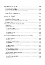
Page 156: ...9 Starting Motor 9 1 2 Components 141 ...

Page 157: ...9 Starting Motor 9 1 3 Troubleshooting 142 ...

Page 158: ...ee the disassembly drawing 2 Screw M4 2 3 Through bolt M5 2 4 Rear cover 5 Brush holder 6 Yoke assy 7 Armature 8 Bolt M6 2 9 Magnetic switch 10 Dust cover 11 Shift lever 12 Screw M4 3 13 Bearing retainer 14 Gear case 15 Pinion stopper clip 16 Pinion stopper 17 Return spring 18 Pinion shaft 19 Clutch assy Disassembly drawing 143 ...

Page 159: ...ar cover Remove the M4 screw fastening the brush holder and remove through bolt M5 for rear cover removal 5 Brush holder Pull the brush spring up with the brush spring puller On the negative side bring the brush spring into contact with the side of the brush for lifting from the commutator surface On the positive side extract the brush from the brush holder 144 ...

Page 160: ...rush holder The armature and yoke assy can now be removed 8 Bolt M6 2 9 Magnetic switch Remove bolt M6 10 mm and the magnetic switch can be removed 10 Dust cover 11 Shift lever Take the dust cover out from the gear case The shift lever can be removed 145 ...

Page 161: ... bearing retainer at the edge and the bearing and shift the pinion stopper toward the pinion use a plain screwdriver and pry to remove the pinion stopper clip 16 Pinion stopper 17 Return spring 18 Pinion shaft 19 Clutch Assy Remove the pinion stopper clip The pinion stopper return spring pinion shaft and bearing retainer can be removed Disassembly is completed now 146 ...

Page 162: ...imit 36 5 35 5 b Armature coil continuity test Check continuity between commutator segments with a multimeter Good if continuity exists In case of no continuity coil disconnection replace the armature c Armature coil insulation test Inspect the continuity between a commutator segment and the shaft or core with a multimeter Good if no continuity exists If continuity exists coil short circuit replac...

Page 163: ...mit is exceeded mm Standard Limit Armature 0 03 0 2 Commutator 0 03 0 2 e Commutator surface inspection If the commutator surface is roughened grind with 500 to 600 emery cloth f Commutator insulation depth Measure the depth of the insulating material between commutator segments and correct it if it is less than the limit mm Standard Limit 0 5 0 8 0 2 148 ...

Page 164: ...ity coil disconnection replace the field coil b Field coil insulation test Check continuity between field coil terminal and yoke Good if no continuity exists If continuity exists coil short circuit replace the armature 3 Brush Measure the length of the brush Replace with a good one if the length is less than the limit mm Standard Limit 15 9 149 ...

Page 165: ...older b Brush spring inspection Inspect the brush spring pressure N kgf Standard spring force 31 39 3 1 3 9 5 Magnetic switch When the starting motor is wetted with water always replace the magnetic switch with a new even if the function is normal a Shunt coil continuity test Check the continuity between the S terminal and the switch body Good if continuity exists If no continuity coil disconnecti...

Page 166: ...ss the magnetic switch with the plunger at the bottom Check continuity between the B and M terminals with a multimeter Good if continuity exists If no continuity coil continuity defect replace the magnetic switch 6 Pinion clutch a Pinion inspection Manually rotate the pinion Inspect if it is rotated smoothly in the driving direction and is locked in the opposite direction Replace the pinion clutch...

Page 167: ...there is play 9 1 6 Service standards Spring force N kgf 35 3 6 Brush Standard height wear limit mm 15 9 Magnetic switch resistance series coil shunt coil at 20 0 27 0 60 Standard diameter limit diameter mm 36 5 35 5 Difference between maximum and minimum diameter Repair limit repair accuracy mm 0 2 0 03 Commutator Mica undercut depth chips Repair limit repair accuracy mm 0 2 0 5 0 8 Armature foun...

Page 168: ...e as below table at all points Pinion and magnetic switch plunger sliding portions NPCFG 6A Gears MALTEMP SRL Shift lever operating portion ALBANIA No 1 2 Magnetic switch assembly 1 Install the shift lever on the magnetic switch with the torsion spring in between 2 For installation on the gear case install the magnetic switch with the shift lever on the gear case after pulling the pinion out Fix t...

Page 169: ...measure the pinion moving distance L in the thrust direction Perform this test within 10 seconds mm Standard L 0 3 1 5 Note Before measuring the dimension pull the pinion out lightly in the direction of the arrow If the measured L dimension is outside the standard range either insert or remove the dust cover adjusting shim 0 5 mm 0 8 mm for adjustment 154 ...

Page 170: ...est quickly since the rating of the starting motor is 30 seconds 1 No load test Fix the starting motor on a test bench and connect wiring as shown in Fig 31 When the switch is closed a current flows in the starting motor which is rotated at no load Measure the current voltage and number of revolutions then and check if they satisfy the specified characteristics 155 ...

Page 171: ...viewed from pinion Clockwise Clutch system Roller clutch Engagement system Magnetic shift Pinion Module number of teeth M3 9 Weight kg 7 3 Pinion projection voltage at 100 V 8 or less Terminal voltage current V A 12 180 or less No load Revolution rpm 3000 or more Terminal voltage current V A 9 500 Torque N m kgfm 16 7 1 7 or more Loaded Revolution min 1 1270 or more 9 2 2 Congiguration drawing 156...

Page 172: ...9 Starting Motor 9 2 3 Troubleshooting 157 ...

Page 173: ...sembly procedure 1 Disconnect the lead 2 Remove the magnetic switch 3 Remove the rear cover 4 Remove the brush holder 5 Disassemble the gear case and center bracket 6 Remove the shift lever pin 7 Remove the gear case dust cover 8 Remove the pinion 2 Disassembly diagram 158 ...

Page 174: ...9 Starting Motor 9 2 5 Disassembly procedure 1 Disconnecting the lead Loosen the M8 nut 12mm of the magnetic switch and disconnect the lead 159 ...

Page 175: ...9 Starting Motor 2 Removal of magnetic switch Remove the M6 bolts 10mm 2 160 ...

Page 176: ...9 Starting Motor 3 Removal of rear cover Remove the brush holder tightening screws 4mm 2 and the M5 through bolts 2 Next disconnect the rear cover from the yoke using a screwdriver 161 ...

Page 177: ...rush bring the brush spring into contact with the side of the brush for lifting from the commutator surface For the positive brush extract the pull out the brush from the brush holder After the brush holder is removed the armature and yoke can be disassembled 162 ...

Page 178: ...ting Motor 5 Separating gear case from center bracket Remove three M6 bolts 10mm fastening the gear case to the center bracket After removal of the M6 bolts the center bracket and oil seal can be removed 163 ...

Page 179: ...9 Starting Motor 6 Removal of shift lever pin Remove the M6 nut 10mm and pull out the shift lever pin Now the dustcover shift lever gear case and gear shaft can be removed 164 ...

Page 180: ...9 Starting Motor 7 Removal of gear case dust cover Remove the two M5 bolts using 4 mm hexagon wrench to disassemble the dust cover from the gear case 165 ...

Page 181: ...9 Starting Motor 8 Removal of pinion Slide the pinion stopper towards the pinion and remove the pinion stopper clip using a screwdriver 166 ...

Page 182: ...or for rough surface If so smooth the surface using 500 to 600 emery cloth If the outside periphery of the commutator has been deflected over 0 2 mm repair by a lathe 2 Measure the depth of the insulating material between commutator segments and correct if it is less than 0 2 mm 167 ...

Page 183: ... continuity and earth tests Test type Measurement point Normal Abnormal cause Continuity test Across commutator Yes None open circuit Earth test Between commutator and shaft or armature None Yes short circuiting Replace if needed 168 ...

Page 184: ... coil continuity and earth tests Test type Measurement point Normal Abnormal cause Continuity test Across commutator Yes None open circuit Earth test Between commutator and shaft or armature None Yes short circuiting Replace if needed 169 ...

Page 185: ...9 Starting Motor 3 Brush 1 Check wear of the brush and the brush spring force 170 ...

Page 186: ...pect the brush holder for bending and the brush holder sliding surface for dirt Repair or clean as needed 3 Check the continuity between the insulated brush holder positive and the brush holder base negative If they are electrically continuous replace since the holder is grounded 171 ...

Page 187: ...inuity test Test type Measurement point Normal Abnormal cause Shunt coil Between C and ground Yes None open circuit Series coil C and M None Yes short circuiting Replace if needed S13 138 Resistance at 20 Shunt coil 0 6 Series coil 0 218 172 ...

Page 188: ...ly grease as instructed below Greasing point Grease type Sliding portions and head of plunger Pinion metal and metal portions of gear case Spline portions of pinion Sliding portions of shift lever NPC FC6A Grease Deceleration gear MALTEMP SRL Grease 2 Armature thrust No adjustments are needed for the thrust 3 Gear shaft thrust Some thrust washers of 1 0 and 0 25 mm thickness are provided between t...

Page 189: ...tion length L by magnetic switch Measure the pinion moving distance L 0 3 to 1 5mm in the thrust direction when the pinion is protruded by the magnetic switch If the distance L is outside the standard range adjust by the dust cover as shown below 174 ...

Page 190: ...Limit 0 2 Commutator Depth of insulation mica Correction accuracy 0 5 0 8 Front 25 Armature shaft diameter Rear 12 Gear shaft diameter 13 95 13 968 Bearing on gear case side Hole diameter 14 00 14 018 Shaft diameter 13 95 13 968 Standard dimensions Sliding portion of pinion Hole diameter 14 03 14 05 Front 6905DDU Ball bearing Armature Rear 6001DDU Length L pinion projection length 0 3 1 5 ...

Page 191: ...entative example of alternator the alternator of 40A is shown in this chapter 10 1 The 40A Alternator for 3TNV84 and other models 10 1 1 Components 1 Parts related to the alternator 2 Alternator components of the disassembly and assembly 176 ...

Page 192: ...iewed from pulley Clockwise Integrated regulator IC regulator Weight kg 2 8 Pulley outside diameter mm 69 2 Belt shape Type A 10 1 3 Wiring diagram NOTICE 1 Don t do miss wiring and short circuit of each terminal 2 Don t short circuit between IG and L Connect it through the charge lamp 3 Don t connect a load between L and E 4 Don t remove a battery terminal and a B terminal when rotating 5 Shut ou...

Page 193: ...e If necessary replace the V belt set 2 V belt tension Refer to 2 2 2 in Chapter 2 2 Visual check of wiring and check of unusual sound 1 Confirm whether wiring is right or there is no looseness of the terminal part 2 Confirm that there is no unusual sound from the alternator during the engine operation 3 Inspection of charge lamp circuit 1 Move a start switch to the position of on Confirm lighting...

Page 194: ...10 Alternator 179 10 1 6 Troubleshooting ...

Page 195: ...11 Electric Wiring 180 11 ELECTRIC WIRING 11 1 Electric Wiring Diagram ...

Page 196: ...t such prior consultation 4 Non use of the Yanmar wiring diagram Use without prior consultation of any wiring diagram other than that provided by Yanmar removes any breakdown of any electrical equipment from the warranty 5 Regarding lamp control Once the charge lamp goes out after the start of charging it does not come on again even if the engine speed falls and charging is insufficient The lamp w...

Page 197: ...he resistance is higher than the specified value This can also cause welding of the magnet switch at the point of contact and resultant burning of the armature coil 4 When there is no safety relay Over running when the electric current flows for too long is a major cause of starting failure This burns the armature coil and causes clutch failure Excessive work and failure of the key switch to retur...

Page 198: ...cable during operation The current limiter may malfunction if the battery cable and or battery are removed during operation depending on the kind of electrical equipment being used causing loss of control over the output voltage In such cases the current limiter and other electrical equipment will be damaged by the generation of a continuous high voltage of 24 43V for 5 000rpm dynamo All electrica...

Page 199: ... 23 20 41 0 80 0 000887 2 25 22 55 56 37 30 70 0 80 0 000520 3 85 38 46 96 15 40 85 0 80 0 000428 4 67 46 73 116 82 50 108 0 80 0 000337 5 93 59 35 148 37 60 127 0 80 0 000287 6 97 69 69 174 22 85 169 0 80 0 000215 9 30 93 02 232 56 100 217 0 80 0 000168 11 90 119 05 297 62 Note1 Allowable maximum resistance of Battery cable Note2 Allowable maximum resistance of Starting motor circuit 2 Terminal r...

Page 200: ...88 106 3 43 35 0 1 1 2 75 28 0 1 1 3 3 3TNV82A 84 1 8 3TNV84T 88 2 0 4TNV84 T 88 2 7 4TNV94L 98 T 4 2 5 Coolant water Capacity Only engine body Liter 4TNV106 T 6 0 2 2 1 4 Full Effective 3TNV82A 5 5 1 9 3TNV84 T 88 6 7 2 8 4TNV84 T 88 7 4 3 4 4TNV94L 98 T 10 5 4 5 4TNV106 T CL class 14 0 9 0 6 Lubricating oil capacity oil pan Liter 4TNV106 T VM class 14 0 7 5 2 2 1 3 at rated speed at low idle spe...

Page 201: ...5 0 8 3TNV82A 2 valve head Exhaust 0 30 0 50 0 8 Intake 0 30 0 50 0 8 TNV84 88 2 valve head 4TNV84T 4 valve Exhaust 0 30 0 50 0 8 Intake 0 36 0 56 0 8 4TNV94L 98 T 4 valve head Exhaust 0 35 0 55 0 8 Intake 0 5 0 7 1 0 Valve sink mm 4TNV106 T 4 valve head Exhaust 0 7 0 9 1 2 4 2 5 1 Intake 120 Seat angle Deg Exhaust 90 Valve seat 2 valve 4 valve Seat correction angle deg 40 150 4 2 6 186 ...

Page 202: ...90 Intake Clearance 0 025 0 055 0 15 Guide inside diameter 6 000 6 015 6 08 Valve stem outside diameter 5 945 5 960 5 90 4TNV84T 4 valve head Exhaust Clearance 0 040 0 070 0 17 Guide inside diameter 7 000 7 015 7 08 Valve stem outside diameter 6 945 6 960 6 90 Intake Clearance 0 040 0 070 0 17 Guide inside diameter 7 000 7 015 7 08 Valve stem outside diameter 6 940 6 955 6 90 4TNV94L 4TNV98 T 4 va...

Page 203: ...V84T 4 valve 1 3 4TNV94L 4TNV98 T 4 valve 1 4 Inclination 4TNV106 T 4 valve 1 5 4 2 5 4 4 Rocker arm and shaft mm Model Inspection item Standard Limit Reference page Arm shaft hole diameter 16 000 16 020 16 07 Shaft outside diameter 15 966 15 984 15 94 TNV82A 88 Clearance 0 016 0 054 0 13 Arm shaft hole diameter 18 500 18 520 18 57 Shaft outside diameter 18 470 18 490 18 44 4TNV94L 98 T 106 T Clea...

Page 204: ...25 44 950 44 890 TNV82A TNV88 Wheel side Clearance 0 050 0 100 0 210 Bushing inside diameter 49 990 50 055 50 130 Camshaft outside diameter 49 925 49 950 49 890 Gear side Clearance 0 040 0 130 0 240 Bushing inside diameter 50 000 50 025 50 100 Camshaft outside diameter 49 910 49 935 49 875 Intermediate Clearance 0 065 0 115 0 225 Bushing inside diameter 50 000 50 025 50 100 Camshaft outside diamet...

Page 205: ...ar 0 07 0 15 0 17 Crank gear cam gear idle gear fuel injection pump gear and PTO gear 0 08 0 14 0 16 Lubricating oil pump gear 0 09 0 15 0 17 4TNV94L 4TNV98 T 4TNV106 T Balancer drive gear only for 4TNV106 T 0 12 0 18 0 20 4 3 4 12 2 3 Cylinder block 1 Cylinder block mm Inspection item Standard Limit Reference page 3TNV82A 82 000 82 030 82 200 TNV84 84 000 84 030 84 200 TNV88 88 000 88 030 88 200 ...

Page 206: ... Metal inside diameter 64 016 64 042 63 902 Metal thickness 1 984 1 992 Crank pin 4TNV106 T Clearance 0 054 0 090 0 150 Journal outside diameter 46 952 46 962 46 902 Metal inside diameter 47 000 47 032 Metal thickness 1 987 2 000 3TNV82A Clearance 0 038 0 080 0 150 Journal outside diameter 53 952 53 962 53 902 Metal inside diameter 54 000 54 020 Metal thickness 1 995 1 990 TNV84 88 Selective pairi...

Page 207: ...0 105 880 3TNV82A 16 3 4TNV84 T 24 3 4TNV88 24 4TNV94L 22 4TNV98 T 22 Piston diameter measure position Upward from the bottom end of the piston 4TNV106 T 30 Hole inside diameter 23 000 23 009 23 039 Pin outside diameter 22 995 23 000 22 965 3TNV82A Clearance 0 000 0 014 0 074 Hole inside diameter 26 000 26 009 26 039 Pin outside diameter 25 995 26 000 25 965 TNV84 88 Clearance 0 000 0 014 0 074 Ho...

Page 208: ...roove width 4 015 4 030 4 130 Ring width 3 970 3 990 3 950 Side clearance 0 025 0 060 0 180 TNV88 Oil ring End clearance 0 200 0 400 0 490 Ring groove width 2 040 2 060 Ring width 1 940 1 960 1 920 Side clearance 0 080 0 120 Top ring End clearance 0 250 0 450 0 540 Ring groove width 2 080 2 095 2 195 Ring width 1 970 1 990 1 950 Side clearance 0 090 0 125 0 245 Second ring End clearance 0 450 0 65...

Page 209: ...9 987 30 000 29 959 4TNV94L 98 Clearance 0 025 0 051 0 109 Bushing inside diameter 37 025 37 038 37 068 Pin outside diameter 36 989 37 000 36 961 4TNV106 T Clearance 0 025 0 049 0 107 4 4 5 5 6 Tappet mm Inspection item Standard Limit Reference page Tappet hole block inside diameter 12 000 12 025 12 045 Tappet stem outside diameter 11 975 11 990 11 955 TNV82A 88 Clearance 0 010 0 050 0 090 Tappet ...

Page 210: ...tem Parts Standard Standard Limit Reference page Gear boss diameter 53 05 53 15 Inside clearance of inner rotor Rotor diameter 53 45 53 55 0 3 0 5 0 6 Width across flat of Gear boss 49 45 49 75 Width across flat clearance of inner rotor Width across flat of rotor 49 95 50 05 0 2 0 6 0 7 5 5 1 2 4 Rotor shaft clearance mm Model Inspection item Standard Limit Reference page Gear case bearing I D 12 ...

Page 211: ...86 2 205 8 19 21 Applied 4 3 4 3TNV82A M10 1 25 76 4 80 4 7 8 8 2 TNV84 88 M12 1 5 93 2 98 1 9 5 10 5 4TNV94L 98 M11 1 25 108 1 117 9 11 0 12 0 Bearing cap set bolt 4TNV106 T M14 1 5 186 2 205 8 19 21 Applied 4 4 4 TNV82A 88 M14 1 5 112 7 122 7 11 5 12 5 Crankshaft pulley set bolt 4TNV94L 98 106 T M14 1 5 107 9 127 5 11 0 13 0 Applied 4 3 4 TNV82A 88 M8 1 25 24 4 28 4 2 5 2 9 Fuel nozzle set bolt ...

Page 212: ... 8 0 10 M14 1 5 127 5 147 1 13 15 Hexagon bolt 7T and nut M16 1 5 215 7 235 4 22 24 Use 80 of the value at left when the tightening part is aluminum Use 60 of the value at left for 4T bolts and lock nuts 1 8 9 8 1 0 1 4 19 6 2 0 3 8 29 4 3 0 PT plug 1 2 58 8 6 0 M8 12 7 16 7 1 3 1 7 M10 19 6 25 4 2 0 2 6 M12 24 5 34 3 2 5 3 5 M14 39 2 49 0 4 0 5 0 Pipe joint bolt M16 49 0 58 8 5 0 6 0 Note Lubrica...

Page 213: ......

Reviews: