4. Disassembly, Inspection and Reassembly of Engines
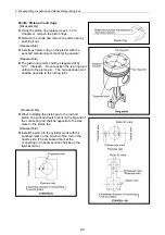
88
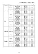
mm
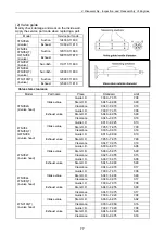
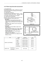
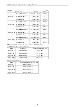
Model Place Item
Standard
Limit
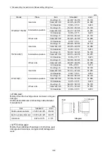
Bushing I.D.
44.990 45.055 45.130
Camshaft O.D.
44.925 44.950 44.890
Gear side
Oil clearance
0.040 0.130 0.240
Bushing I.D.
45.000 45.025 45.100
Camshaft O.D.
44.910 44.935 44.875
Intermediate position
Oil clearance
0.065 0.115 0.225
Bushing I.D.
45.000 45.025 45.100
Camshaft O.D.
44.925 44.950 44.890
3TNV82A TNV88
Wheel side
Oil clearance
0.050 0.100 0.210
Bushing I.D.
49.990 50.055 50.130
Camshaft O.D.
49.925 49.950 49.890
Gear side
Oil clearance
0.040 0.130 0.240
Bushing I.D.
50.000 50.025 50.100
Camshaft O.D.
49.910 49.935 49.875
Intermediate position
Oil clearance
0.065 0.115 0.225
Bushing I.D.
50.000 50.025 50.100
Camshaft O.D.
49.925 49.950 49.890
TNV94L/98(T)
Wheel side
Oil clearance
0.05 0.100 0.210
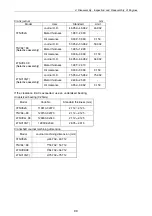
Bushing I.D.
57.980 58.050 58.105
Camshaft O.D.
57.910 57.940 57.875
Gear side
Oil clearance
0.040 0.140 0.250
Bushing I.D.
58.000 58.030 58.105
Camshaft O.D.
57.895 57.925 57.860
Intermediate position
Oil clearance
0.075 0.135 0.245
Bushing I.D.
58.000 58.030 58.105
Camshaft O.D.
57.910 57.940 57.875
4TNV106(T)
Wheel side
Oil clearance
0.050 0.120 0.230
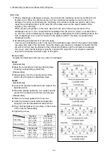
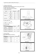
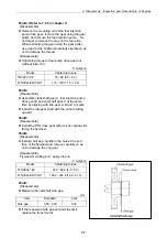
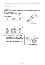
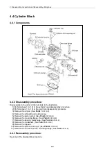
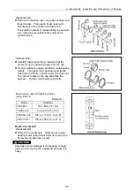
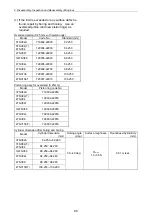
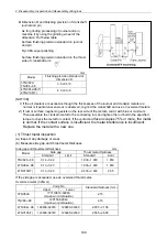
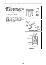
(2) Idle gear
Mainly check the bushing seizure and wear, and gear
damage.
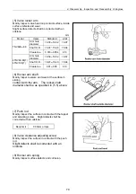
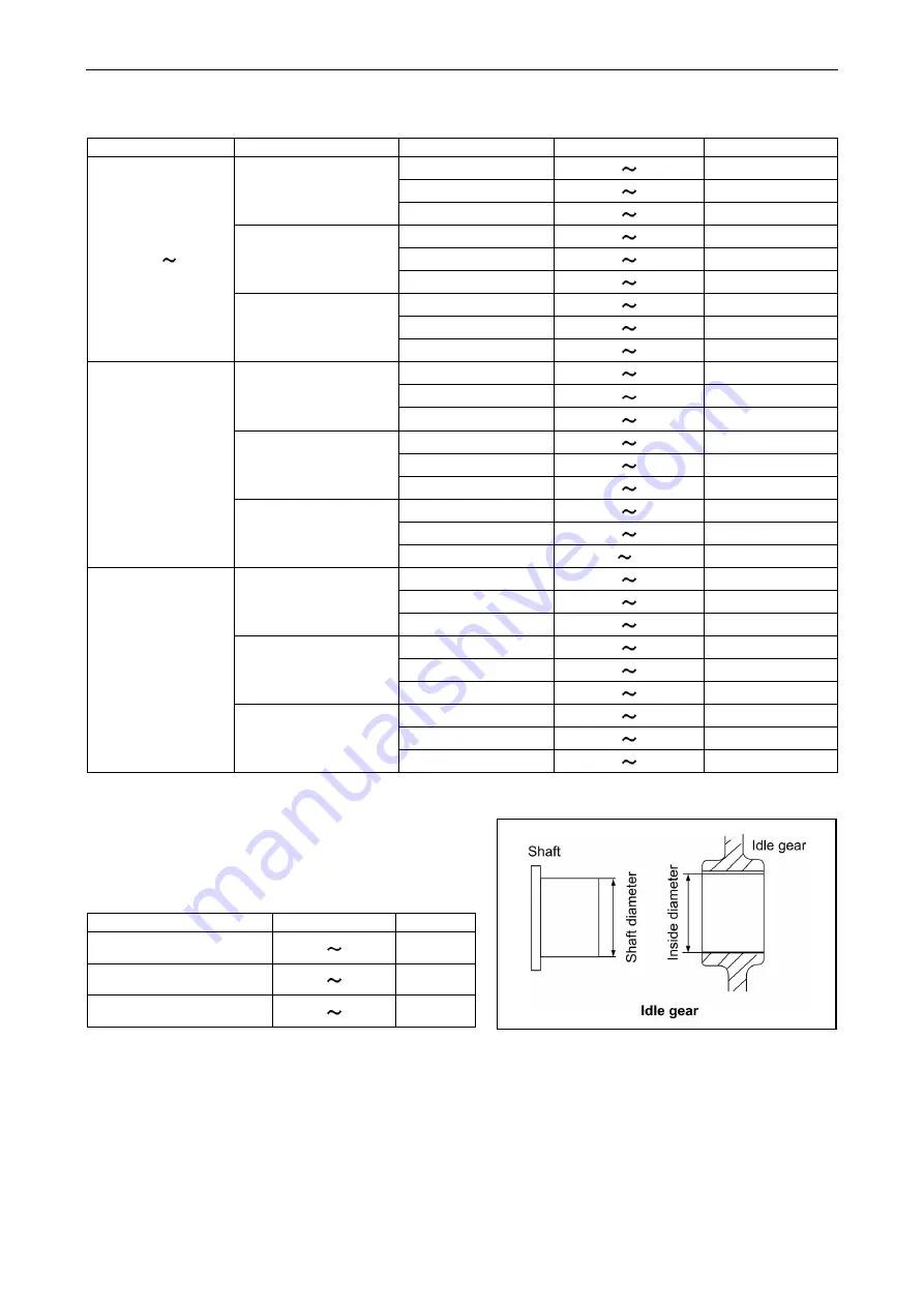
Shaft outside diameter and bushing inside diameter
measurement
mm
Item Standard
Limit
Shaft outside diameter
45.950 49.975
45.900
Bushing inside diameter 46.000 46.025
46.075
Clearance 0.025 0.075 0.175
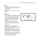
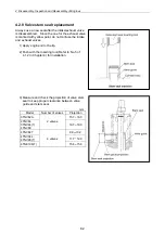
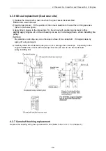
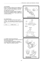
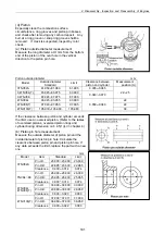
(3) PTO drive gear
Mainly check sticking of bearings on both sides, gear
damage and looseness, and gear shaft damage and
wear.
Summary of Contents for 3TNV Series
Page 1: ...4TNV106 4TNV106T 4TNV94L 4TNV98 4TNV98T 3TNV82A 3TNV84 T 4TNV84 T 3TNV88 4TNV88 ...
Page 31: ...1 General 1 4 Engine External Views 16 ...
Page 32: ...1 General 1 5 Structural Description 17 ...
Page 156: ...9 Starting Motor 9 1 2 Components 141 ...
Page 157: ...9 Starting Motor 9 1 3 Troubleshooting 142 ...
Page 172: ...9 Starting Motor 9 2 3 Troubleshooting 157 ...
Page 175: ...9 Starting Motor 2 Removal of magnetic switch Remove the M6 bolts 10mm 2 160 ...
Page 185: ...9 Starting Motor 3 Brush 1 Check wear of the brush and the brush spring force 170 ...
Page 194: ...10 Alternator 179 10 1 6 Troubleshooting ...
Page 195: ...11 Electric Wiring 180 11 ELECTRIC WIRING 11 1 Electric Wiring Diagram ...
Page 213: ......


