
4. Disassembly, Inspection and Reassembly of Engines
94
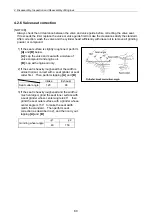
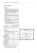
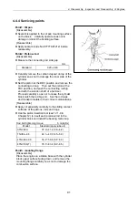
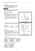
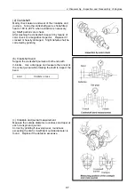
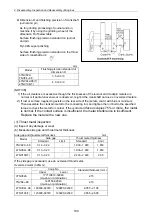
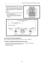
Point6: Piston pin and rings
[Disassemble]
Using the piston ring replacer (see 4.1.2 in
Chapter 4), remove the piston rings.
Remove the circlip and remove the piston pin by
pushing it out.
[Reassemble]
Install each piston ring on the piston, with the
punched manufacturer’s mark facing upward.
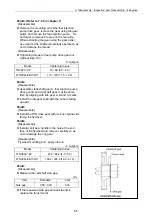
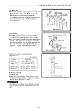
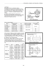
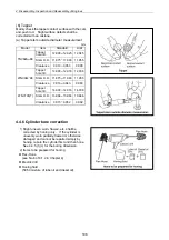
[Reassemble]
The piston ring joints shall be staggered at by
120
°
intervals. Do not position the top ring joint
vertical to the piston pin. The coil expander joint
shall be opposite to the oil ring joint.
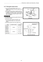
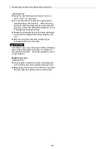
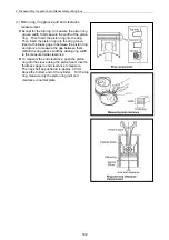
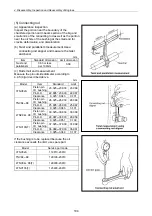
[Reassemble]
When installing the piston pin to the rod and
piston, the punched match mark on the big end of
the connecting rod shall be opposite to the size
mark on the piston top.
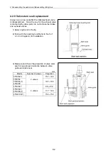
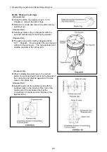
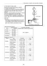
[Reassemble]
Install the piston in the cylinder clock with the
punched mark on the big end of the rod on the
nozzle side. (The embossed mark at the
connecting rod I-beam section shall be on the
flywheel side.)
Summary of Contents for 3TNV Series
Page 1: ...4TNV106 4TNV106T 4TNV94L 4TNV98 4TNV98T 3TNV82A 3TNV84 T 4TNV84 T 3TNV88 4TNV88 ...
Page 31: ...1 General 1 4 Engine External Views 16 ...
Page 32: ...1 General 1 5 Structural Description 17 ...
Page 156: ...9 Starting Motor 9 1 2 Components 141 ...
Page 157: ...9 Starting Motor 9 1 3 Troubleshooting 142 ...
Page 172: ...9 Starting Motor 9 2 3 Troubleshooting 157 ...
Page 175: ...9 Starting Motor 2 Removal of magnetic switch Remove the M6 bolts 10mm 2 160 ...
Page 185: ...9 Starting Motor 3 Brush 1 Check wear of the brush and the brush spring force 170 ...
Page 194: ...10 Alternator 179 10 1 6 Troubleshooting ...
Page 195: ...11 Electric Wiring 180 11 ELECTRIC WIRING 11 1 Electric Wiring Diagram ...
Page 213: ......


