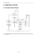
5. Lubrication System
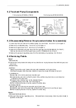
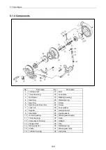
5.2 Trochoid Pump Components
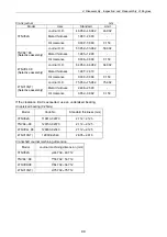
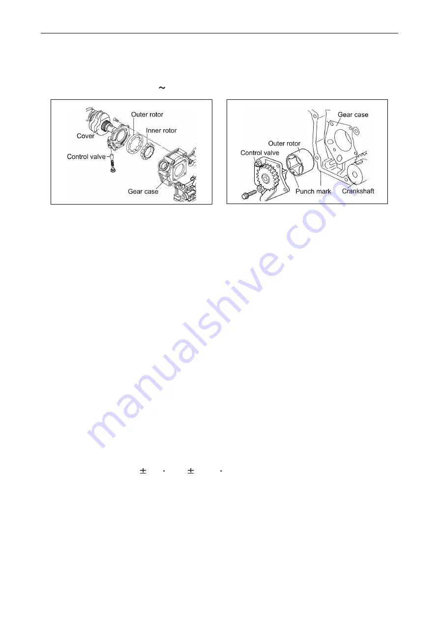
Trochoid pump (3TNV82A TNV88)
Trochoid pump (4TNV94L/98/106)
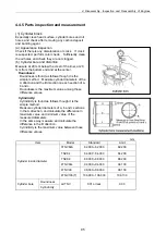
5.3 Disassembly(Reverse the procedure below for assembly)
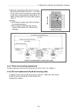
1) Loosen the belt, and remove the radiator pulley, fan and V-belt. See 4.2.2. 2) in Chapter 4.
2) Remove the crankshaft pulley. See 4.3.2. 3) in Chapter 4.
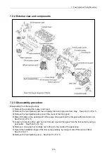
3) Remove the gear case cover. See 4.3.2. 4) in Chapter 4.
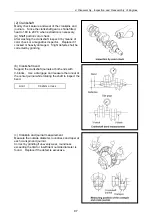
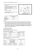
4) Remove the lubricating oil pump assy from the gear case for 4TNV94/98/106. (5.4 Point 1)
Remove the lube oil cover from gear case cover for 3TNV82A-88. (5.4 Point 1)
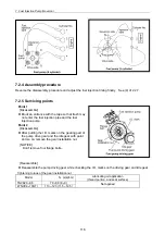
5) Remove the pressure regulating valve from the lubricating oil pump body. (5.4 Point 2)
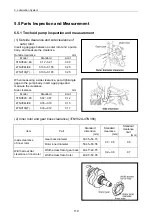
5.4 Servicing Points
Point 1
[Disassemble]
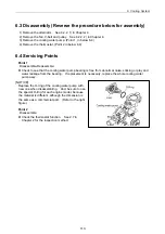
Check if the pump rotates smoothly and see that there is no play between the shaft and gear, and
inner rotor.
[Reassemble]
[NOTICE]
Always check if the pump rotates smoothly after installation on the gear case.
Running the engine when the pump rotation is heavy may cause the pump to be burnt.
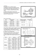
1) 3TNV82A-88
Apply lube oil to rotor (outer/inner) insertion part.
Assemble the outer rotor so that the mark of the end face may become a cover side when
inserting it in the gear case.
Fasten a lube oil pump cover by the standard torque.
Tightening torque: 6.9 1.5N m (0.7 0.15kgf m)
When replacing the lube oil pump, replace the whole assy.
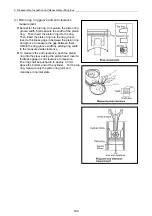
2) 4TNV94L/98/106
Apply lube oil to lube oil pump insertion part of gear case.
Install the outer rotor in the gear case so that the punch mark on the end face is seen.
When replacing the lube oil pump, replace the whole assy.
Point 2
[Disassemble-Reassemble]
Only wash the pressure regulating valve. Disassembly is unnecessary unless any abnormality in
operation is detected.
109
Summary of Contents for 3TNV Series
Page 1: ...4TNV106 4TNV106T 4TNV94L 4TNV98 4TNV98T 3TNV82A 3TNV84 T 4TNV84 T 3TNV88 4TNV88 ...
Page 31: ...1 General 1 4 Engine External Views 16 ...
Page 32: ...1 General 1 5 Structural Description 17 ...
Page 156: ...9 Starting Motor 9 1 2 Components 141 ...
Page 157: ...9 Starting Motor 9 1 3 Troubleshooting 142 ...
Page 172: ...9 Starting Motor 9 2 3 Troubleshooting 157 ...
Page 175: ...9 Starting Motor 2 Removal of magnetic switch Remove the M6 bolts 10mm 2 160 ...
Page 185: ...9 Starting Motor 3 Brush 1 Check wear of the brush and the brush spring force 170 ...
Page 194: ...10 Alternator 179 10 1 6 Troubleshooting ...
Page 195: ...11 Electric Wiring 180 11 ELECTRIC WIRING 11 1 Electric Wiring Diagram ...
Page 213: ......


