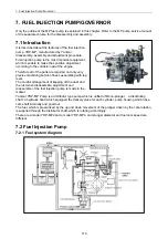
7. Fuel Injection Pump/Governor
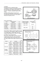
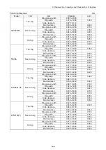
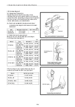
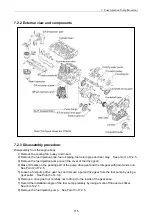
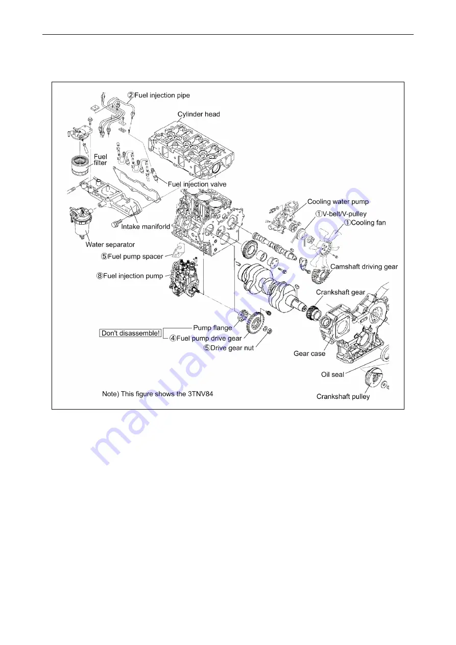
7.2.2 External view and components
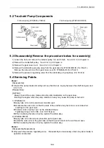
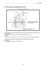
7.2.3 Disassembly procedure:
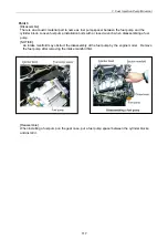
Disassembly from the engine body
1) Remove the cooling fan, pulley and V-belt.
2) Remove the fuel injection pipe, fuel oil piping, fuel return pipe and rear stay. See point 1 of 7.2.5.
3) Remove the fuel injection pump cover (the cover of the drive gear).
4) Make ID marks on the gearing part of the pump drive gear and the idle gear with paint and so on.
See Point 2 of 7.2.5.
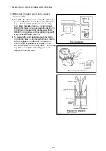
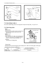
5) Loosen a fuel pump drive gear nut, and remove a pump drive gear from the fuel pump by using a
gear puller. See Point 3 of 4.3.4.
6) Remove a drive gear nut carefully not to drop it to the inside of the gear case.
7) Record the installation angle of the fuel pump precisely by using a mark-off line and a sticker.
See (4) of 2.2.7.
8) Remove the fuel injection pump. See Point 3 of 7.2.5.
115
Summary of Contents for 3TNV Series
Page 1: ...4TNV106 4TNV106T 4TNV94L 4TNV98 4TNV98T 3TNV82A 3TNV84 T 4TNV84 T 3TNV88 4TNV88 ...
Page 31: ...1 General 1 4 Engine External Views 16 ...
Page 32: ...1 General 1 5 Structural Description 17 ...
Page 156: ...9 Starting Motor 9 1 2 Components 141 ...
Page 157: ...9 Starting Motor 9 1 3 Troubleshooting 142 ...
Page 172: ...9 Starting Motor 9 2 3 Troubleshooting 157 ...
Page 175: ...9 Starting Motor 2 Removal of magnetic switch Remove the M6 bolts 10mm 2 160 ...
Page 185: ...9 Starting Motor 3 Brush 1 Check wear of the brush and the brush spring force 170 ...
Page 194: ...10 Alternator 179 10 1 6 Troubleshooting ...
Page 195: ...11 Electric Wiring 180 11 ELECTRIC WIRING 11 1 Electric Wiring Diagram ...
Page 213: ......


