8. Turbochager
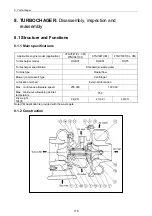
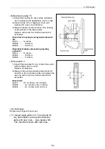
8.1.3 Structural and functional outline
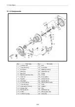
No. Part
name
1
2
3
4
5
6
7
8
9
10
11
12
13
14
15
16
17
18
19
20
Turbine shaft
OiN thrower
Turbine side seal ring
Seal plate
Journal bearing
Thrust bearing
Compressor housing
M5 hexagon bolt
M5 spring washer
Compressor side clamp
Turbine housing
M6 hexagon bolt
Turbine side clamp
Lock washer
Bearing housing
Retaining ring
M3 countersunk flat head screw
Compressor wheel
Shaft end nut
Heat protector
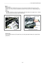
(1) Turbine
The exhaust gas from the engine is accelerated at the nozzle portion in the turbine housing and blown
onto the turbine impeller to rotate the turbine shaft.
This is called the turbine. A seal ring and heat insulating plate are installed to prevent the bearing from
adverse influence of the gas.
(2) Compressor
The compressor impeller installed on the turbine shaft rotates with the shaft to suck and compress air
for feeding into the intake manifold.
This is called the blower or compressor.
(3) Bearings
Thrust bearing
As the turbine shaft is constantly applied with a thrust force, this bearing prevents the shaft from
being moved by the thrust force.
Radial bearing
A floating bearing is adopted. Since the bearing moves with the turbine shaft as the oil films are
formed both inside and outside the bearing, the bearing sliding speed is slower than the turbine shaft
speed, resulting in higher dynamic stability.
(4) Compressor side sealing mechanism
To prevent the intake air and oil form leaking, a seal ring and a seal plate are provided to form a double
wall structure on the rear side of the compressor impeller.
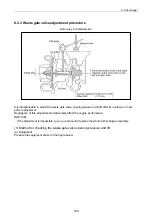
(5) Waste gate
When the blower side pressure (intake air pressure) exceeds the specified level, the exhaust gas at the
turbine inlet is partially bypassed to the exhaust discharge side to control the turbine rpm so as to
maintain the intake pressure at the specified level for improving the response to load variation in the low
to medium speed range and to minimize black smoke generation. It consists of a control assembly
separated from the turbocharger and a valve assembly installed in the turbine impeller chamber.
119
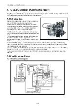
Summary of Contents for 3TNV Series
Page 1: ...4TNV106 4TNV106T 4TNV94L 4TNV98 4TNV98T 3TNV82A 3TNV84 T 4TNV84 T 3TNV88 4TNV88 ...
Page 31: ...1 General 1 4 Engine External Views 16 ...
Page 32: ...1 General 1 5 Structural Description 17 ...
Page 156: ...9 Starting Motor 9 1 2 Components 141 ...
Page 157: ...9 Starting Motor 9 1 3 Troubleshooting 142 ...
Page 172: ...9 Starting Motor 9 2 3 Troubleshooting 157 ...
Page 175: ...9 Starting Motor 2 Removal of magnetic switch Remove the M6 bolts 10mm 2 160 ...
Page 185: ...9 Starting Motor 3 Brush 1 Check wear of the brush and the brush spring force 170 ...
Page 194: ...10 Alternator 179 10 1 6 Troubleshooting ...
Page 195: ...11 Electric Wiring 180 11 ELECTRIC WIRING 11 1 Electric Wiring Diagram ...
Page 213: ......


